Phase detector, phase-frequency detector, and digital phase locked loop

a phase detector and phase-frequency technology, applied in the direction of oscillation comparator circuits, automatic control of pulses, instruments, etc., can solve the problem of likely change in the bandwidth of the entire phase locked loop

Active Publication Date: 2015-01-08
SK HYNIX INC +1
View PDF3 Cites 28 Cited by
  • Summary
  • Abstract
  • Description
  • Claims
  • Application Information

AI Technical Summary

Benefits of technology

[0019]In an embodiment of the present disclosure, a digital phase locked loop includes: an offset controller configured to dither an offset control signal and output a control signal; a phase detector configured to detect a phase difference between a first clock signal and a second clock signal according to the control signal and output a phase detection signal; a filter configured to filter the phase detection signal; a digital oscillator configured to generate a third clock signal based on an output of the filter wherein an initial frequency of the third clock signal is controlled according to an initialization signal; and a feedback circuit configured to divide the third clock signal and generate the second clock signal.
[0020]In an embodiment of the present disclosure, a phase-frequency detector includes: a first flip-flop configured to latch a power supply voltage according to a first clock signal and output a first internal clock signal; a second flip-flop configured to latch the power supply voltage according to a second clock signal and output a second internal clock signal; a reset circuit configured to logically combine the first internal clock signal and the second internal clock signal and generate a reset signal to reset the first flip-flop and the second flip-flop; a timing controller configured to generate a third internal clock signal by delaying the first internal clock signal, to generate a fourth internal clock signal by delaying the second internal clock signal and to generate a control signal by logically combining the is external control signal where the control signal is aligned with the fourth internal clock signal; and a phase detector configured to detect a phase difference between the third internal clock signal and the fourth internal clock signal according to the control signal, and output a phase detection signal.
[0021]In an embodiment of the present disclosure, a digital phase locked loop includes: a phase-frequency detector configured to detect differences in phases and frequencies between a first clock signal and a second clock signal according to an external control signal, and output a phase-frequency detection signal; an offset controller configured to dither an of

Problems solved by technology

As a result, the bandwidth of the entir

Method used


Image

  • Phase detector, phase-frequency detector, and digital phase locked loop
  • Phase detector, phase-frequency detector, and digital phase locked loop
  • Phase detector, phase-frequency detector, and digital phase locked loop

Examples


Embodiment Construction

[0042]Hereinafter, embodiments of a phase detector, a phase-frequency detector, and a digital phase locked loop including the same will be described with reference to the accompanying drawings. Throughout the disclosure, identical reference numerals refer to identical parts throughout the various figures and embodiments of the present disclosure.

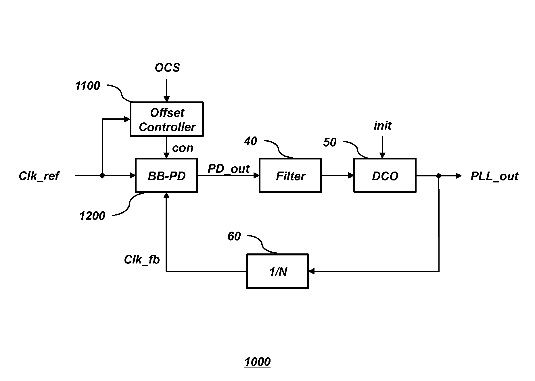
[0043]FIG. 3 is a block diagram of a DPLL 1000 including a BB-PD 1200 in accordance with an embodiment of the present disclosure. The DPLL 1000 includes an offset controller 1100, the BB-PD 1200, a filter 40, a DCO 50, and a feedback circuit 60. Because the filter 40, the DCO 50, and the feedback circuit 60 are, in light of the teachings and disclosures herein, generally known to those of ordinary skill in the art, detailed descriptions thereof are omitted herein.

[0044]The offset controller 1100 outputs a control signal con based on a reference clock signal Clk_ref and an offset control signal OCS. As will be described below, the control sig...


PUM


Abstract

A phase detector includes a phase comparing circuit configured to detect and output a phase difference between a first clock signal and a second clock signal, a latch circuit configured to latch an output signal of the phase comparing circuit and output a phase detection signal, and an initial voltage control circuit configured to control an initial voltage of an input terminal of the latch circuit according to a control signal.

Description

CROSS-REFERENCES TO RELATED APPLICATION[0001]The present application claims priority under 35 U.S.C. §119(a) to Korean Patent Application Number 10-2013-0079411, filed on Jul. 8, 2013 and Korean Patent Application Number 10-2014-0074821, filed on Jun. 19, 2014, in the Korean intellectual Property Office, which is incorporated herein by reference in its entirety.BACKGROUND[0002]1. Technical Field[0003]Embodiments relate to a phase detector, a phase-frequency detector, and a digital phase locked loop, and more particularly, to a phase detector and a phase-frequency detector in which output timing is controlled according to a control signal and a digital phase locked loop including the same.[0004]2. Related Art[0005]Research has been conducted to develop a digital phase locked loop for use in place of an analog phase locked loop. A conventional digital phase locked loop (DPLL) may include a time digital converter (TDC). A bang-bang type phase detector may be used to reduce power consum...

Claims


Application Information

Patent Timeline
IPC IPC(8): H03L7/097H03L7/085
CPCH03L7/085H03L7/097
Inventor KIM, YOUNG-HOONJANG, SOO-YOUNGYOO, CHANG-SIKJEONG, CHUN-SEOKLEE, KANG-SEOL
Owner SK HYNIX INC
Why Eureka
Try Eureka