Control apparatus for internal combustion engine

a control apparatus and internal combustion engine technology, applied in the direction of engine controllers, combustion engines, machines/engines, etc., to achieve the effect of improving the responsiveness of the intake air amoun

Active Publication Date: 2015-01-15
TOYOTA JIDOSHA KK
View PDF12 Cites 2 Cited by
  • Summary
  • Abstract
  • Description
  • Claims
  • Application Information

AI Technical Summary

Benefits of technology

[0028]Thus, in a region that is equal to or higher than the medium load region, an even larger margin for control of the intake air amount (intake pipe pressure) by the throttle valve can be secured. It is thereby possible to further improve the responsiveness of the intake air amount when a request is made to increase the intake air amount at a rate that is equal to or greater than the predetermined rate under a low atmospheric pressure.

Problems solved by technology

That is, in this case, since it is not possible to secure a margin for control of the intake air amount (intake pipe pressure) by the throttle valve, intake air amount control is executed that is dependent on the turbo-supercharger with respect to which the responsiveness is low.

Method used


Image

  • Control apparatus for internal combustion engine
  • Control apparatus for internal combustion engine
  • Control apparatus for internal combustion engine

Examples


first embodiment

Explanation of System Configuration

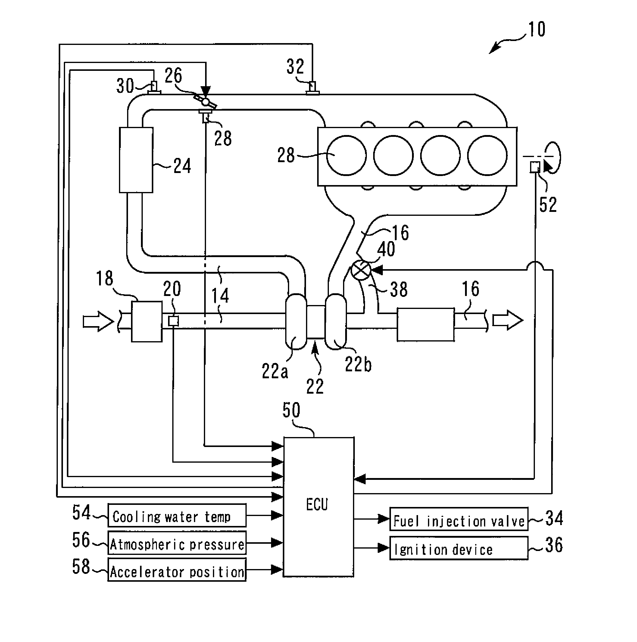
[0035]FIG. 1 is a schematic view for describing the system configuration of an internal combustion engine 10 of a first embodiment of the present invention. A system of the present embodiment includes a spark ignition type internal combustion engine (as one example, a gasoline engine) 10. A combustion chamber 12 is formed inside each cylinder of the internal combustion engine 10. An intake passage 14 and an exhaust passage 16 communicate with the combustion chamber 12.

[0036]An air cleaner 18 is installed in the vicinity of an inlet of the intake passage 14. An air flow meter 20 that outputs a signal in accordance with a flow rate of air that is drawn into the intake passage 14 is provided in the vicinity of the air cleaner 18 on a downstream side thereof. A compressor 22a of a turbo-supercharger 22 is arranged downstream of the air flow meter 20. The compressor 22a is integrally connected through a connecting shaft (not illustrated in the drawings)...

second embodiment

[0068]Next, a second embodiment of the present invention will be described with reference to FIG. 5.

[0069]It is assumed that a system of the present embodiment includes the hardware configuration shown in FIG. 1, and executes similar control to the above described first embodiment. On that basis, the present embodiment is configured so that restriction of the operating speed of the throttle valve 26 described hereunder is performed as necessary.

[0070]FIG. 5 is a time chart for describing control executed in the second embodiment of the present invention when a request to increase the intake air amount with a high response is made under a low atmospheric pressure.

[0071]According to the control under a low atmospheric pressure of the above described first embodiment, when a request to increase the intake air amount with a high response is made, the responsiveness of the intake air amount can be improved by utilizing a margin for control of the intake air amount (intake pipe pressure) ...

third embodiment

[0076]Next, a third embodiment of the present invention will be described referring to FIG. 6.

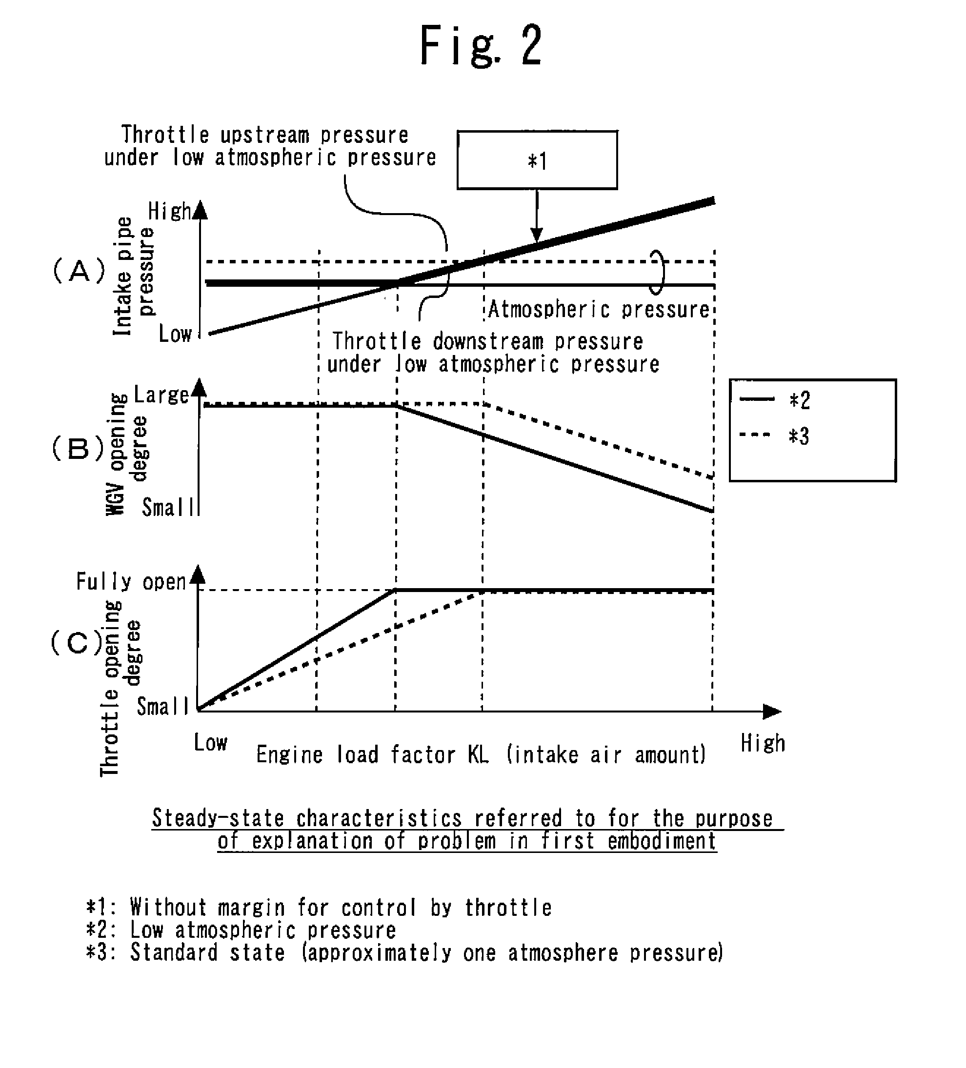
[0077]FIG. 6 has views that illustrate a load factor-throttle steady-state characteristic and load factor-WGV steady-state characteristic that are used in the third embodiment of the present invention. It is assumed that the system of the present embodiment is the same as the system of the first embodiment that is described above, except with respect to the points described hereunder referring to FIG. 6.

[0078]In the above described first embodiment (and second embodiment), a throttle opening degree that is used in the medium load region (KL1 to KL3) under a low atmospheric pressure is set to the predetermined constant opening degree TA1. In contrast, according to the present embodiment, a throttle opening degree that is used in the medium load region under a low atmospheric pressure is set so as to decrease as the engine load factor KL increases, as shown by a thick solid line in FIG. 6(C)....


PUM


Abstract

A control apparatus for an internal combustion engine of the present invention switches a steady-state characteristic that defines a relation between an engine load factor and a throttle opening degree between a high atmospheric pressure steady-state characteristic and a low atmospheric pressure steady-state characteristic in accordance with whether or not the atmospheric pressure is higher than a predetermined value. According to the low atmospheric pressure steady-state characteristic, a throttle opening degree corresponding to an identical engine load factor is set to a smaller value compared to the high atmospheric pressure steady-state characteristic in a medium load region, and the throttle opening degree is set so as to increase as the engine load factor increases towards a full load in a region on the side of a higher load factor than the medium load region.

Description

TECHNICAL FIELD[0001]The present invention relates to a control apparatus for an internal combustion engine, and more particularly to a control apparatus for a supercharged internal combustion engine that includes a turbo-supercharger and a waste gate valve that opens and closes an exhaust bypass passage that bypasses a turbine of the turbo-supercharger.BACKGROUND ART[0002]A control apparatus for an internal combustion engine with a turbo-supercharger that includes a waste gate valve that opens and closes an exhaust bypass passage that bypasses a turbine has already been disclosed in, for example, Patent Document 1. According to the conventional control apparatus, a configuration is adopted so as to open a throttle valve as far as a substantially fully open position when an accelerator pedal is operated as far as a predetermined operation amount. Further, if the accelerator pedal is opened to a greater degree than the predetermined operation amount, a supercharging pressure is contr...

Claims


Application Information

Patent Timeline
Patent Type & Authority Applications(United States)
IPC IPC(8): F02B37/04F02B37/22
CPCF02B37/04F02B37/22F02D23/00F02D11/105F02D2200/703F02B2037/122F02B2037/125F02B37/18Y02T10/12
Inventor NAKASAKA, YUKIHIRO
Owner TOYOTA JIDOSHA KK
Why Eureka
Try Eureka