Ashing device

a technology of ashing device and a spherical plate, which is applied in the direction of photomechanical equipment, instruments, chemistry equipment and processes, etc., can solve the problems of unstable spherical plate rate, and achieve the effect of preventing the spherical plate rate from decreasing over tim

Active Publication Date: 2015-01-15
ULVAC INC
View PDF11 Cites 3 Cited by
  • Summary
  • Abstract
  • Description
  • Claims
  • Application Information

AI Technical Summary

Benefits of technology

[0010]The present invention provides an ashing device that prevents the processing efficiency from decreasing over time.

Problems solved by technology

Such a change in the ashing rate over time leads to a problem in which the ashing rate becomes unstable.

Method used


Image

  • Ashing device
  • Ashing device
  • Ashing device

Examples


Embodiment Construction

[0022]An ashing device according to an embodiment of the present invention will now be discussed with reference to FIGS. 1 to 3.

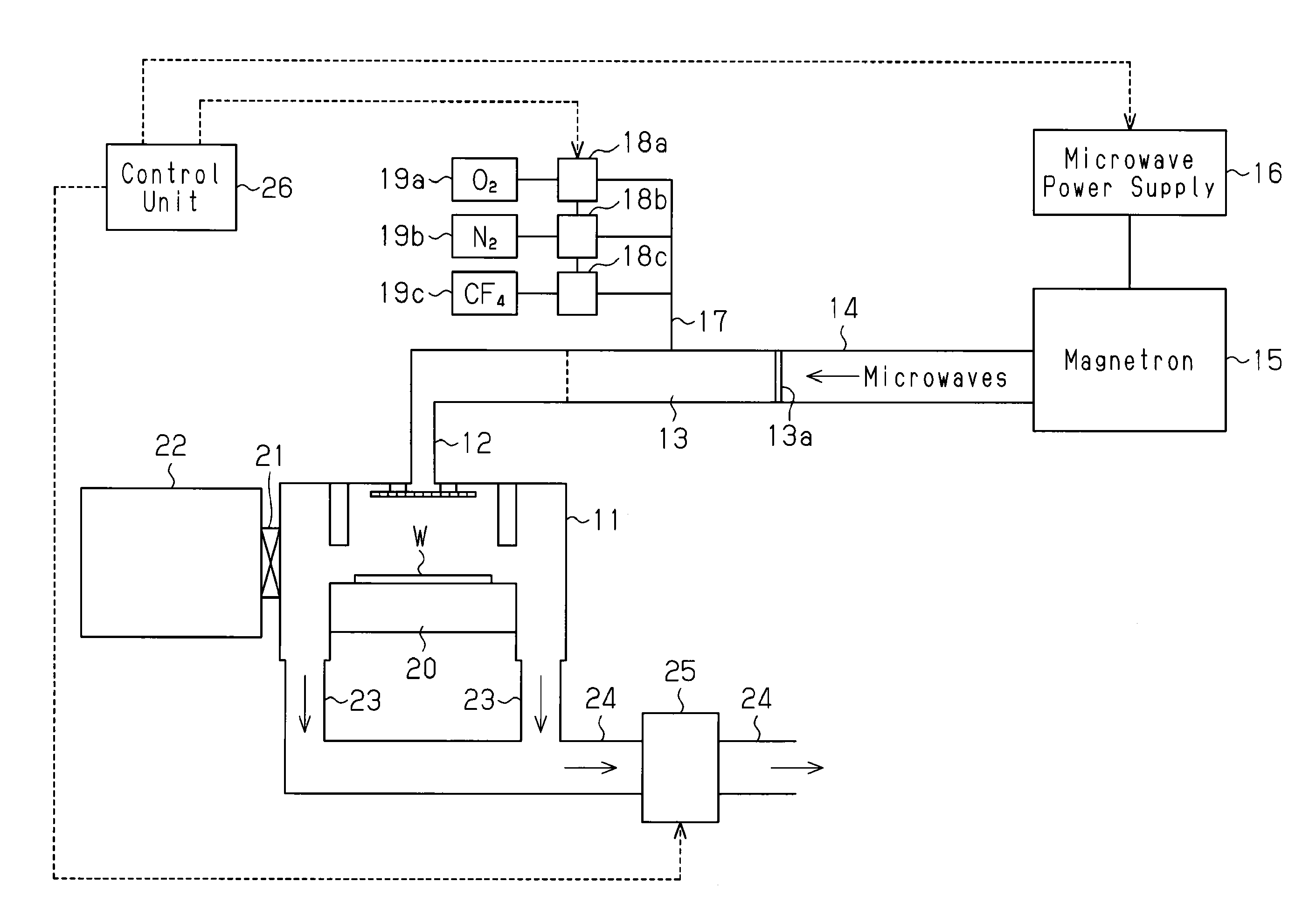
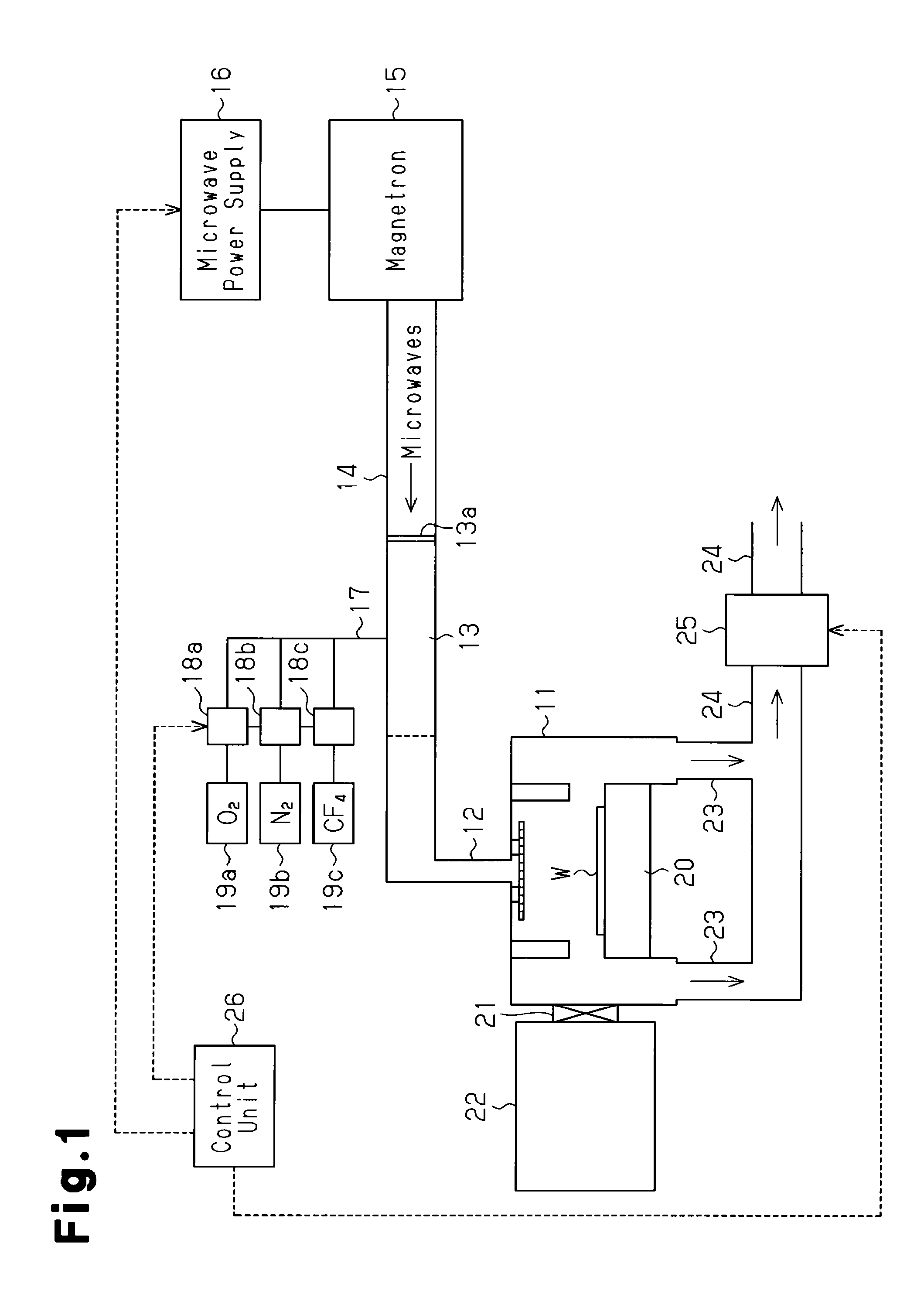
[0023]As shown in FIG. 1, the ashing device includes a chamber (processing chamber) 11, the upper part of which is connected to a plasma chamber 13 by a feed tube 12. The plasma chamber 13 is connected to a magnetron 15 by way of a microwave waveguide 14. A microwave transmissive window 13a, which is formed from silica or the like, partitions the plasma chamber 13 and the microwave waveguide 14. A microwave power supply 16 is connected to the magnetron 15. Microwaves (μ waves) generated in the magnetron 15 are guided to the plasma chamber 13 through the microwave waveguide 14.

[0024]The plasma chamber 13 is connected to a plurality of (three in the drawing) mass flow controllers 18a to 18c by a gas intake tube 17. The mass flow controllers 18a to 18c are respectively connected to gas supply sources 19a to 19c. In the present embodiment, the gas supply source...


PUM

PropertyMeasurementUnit
pressureaaaaaaaaaa
pressureaaaaaaaaaa
frequencyaaaaaaaaaa

Abstract

An ashing device that prevents the ashing rate from changing over time. The ashing device ashes organic material on a substrate including an exposed metal in a processing chamber. The ashing device includes a path, which is formed in the processing chamber and through which active species supplied to the processing chamber pass. The path is defined by a surface on which the metal scattered from the substrate by the active species is collectible, with the surface being formed so as to expose a metal that is of the same kind.

Description

CROSS-REFERENCE TO RELATED APPLICATIONS[0001]The present application is a continuation application of U.S. application Ser. No. 12 / 443,912, filed Apr. 1, 2009, which is a national stage entry of WO Application No. PCT / JP2008 / 069681, filed Oct. 29, 2008, which claims priority to JP Application No. 2007-287341, filed Nov. 5, 2007, all of which are hereby incorporated by reference herein in their entirety.FIELD OF THE INVENTION[0002]The present invention relates to an ashing device for performing ashing (incineration) to remove organic materials from a substrate.BACKGROUND OF THE INVENTION[0003]In the prior art, to form an integrated circuit on a semiconductor substrate, a resist film on which is formed a circuit pattern is arranged on the surface of a semiconductor substrate. Then, layers under the resist film, such as an insulation film, a semiconductor film, or a metal film, are etched through the resist film. The resist film is removed from the substrate surface after ending the et...

Claims


Application Information

Patent Timeline
Patent Type & Authority Applications(United States)
IPC IPC(8): H01L21/02
CPCH01L21/02068G03F7/427H01J37/32192H01J37/32467H01J37/32477H01L21/31138H01L21/3065
Inventor UEDA, MASAHISAKURIMOTO, TAKASHINAKAMURA, KYUZOSUU, KOUKOUYOGO, TOSHIYAKOMATSU, KAZUSHIGETACHIBANA, NOBUSUKE
Owner ULVAC INC
Why Eureka
Try Eureka