
Back contact solar cell

Inactive Publication Date: 2015-01-15
INVENTEC SOLAR ENERGY CORP
View PDF8 Cites 7 Cited by
  • Summary
  • Abstract
  • Description
  • Claims
  • Application Information

AI Technical Summary

Benefits of technology

The invention is about a type of solar cell that has longer electrodes on the front and shorter electrodes on the back, which improves its ability to convert light into electricity.

Problems solved by technology

The upper surface is configured for receiving sunlight, but the top electrodes disposed on the upper surface will block incident sunlight and a photoelectric conversion efficiency of the solar cell will be adversely affected.
It leads to the problem of reduction in the photoelectric conversion efficiency and output of the solar cell.
Moreover, the wider finger electrodes will cause wafer bowing and electrode peeling due to high stress.
That will adversely affect the photoelectric conversion efficiency of the solar cell.

Method used


Image

  • Back contact solar cell
  • Back contact solar cell
  • Back contact solar cell

Examples


Embodiment Construction

[0020]The present invention will now be described more specifically with reference to the following embodiments. It is to be noted that the following descriptions of preferred embodiments of this invention are presented herein for purpose of illustration and description only. It is not intended to be exhaustive or to be limited to the precise form disclosed.

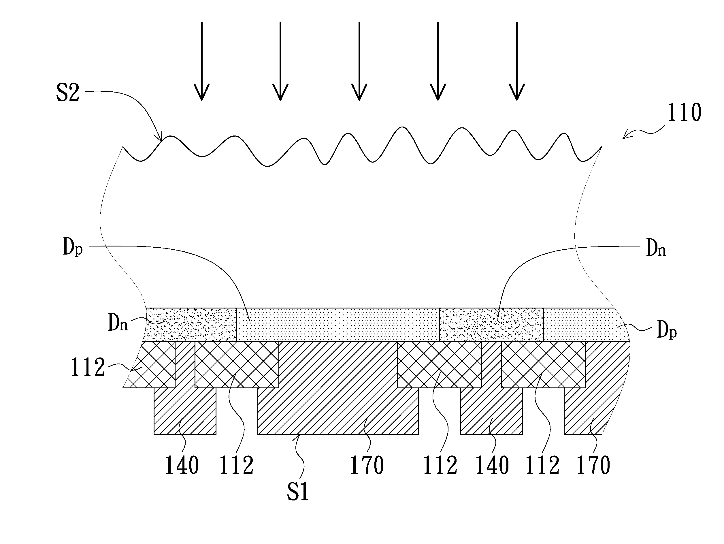
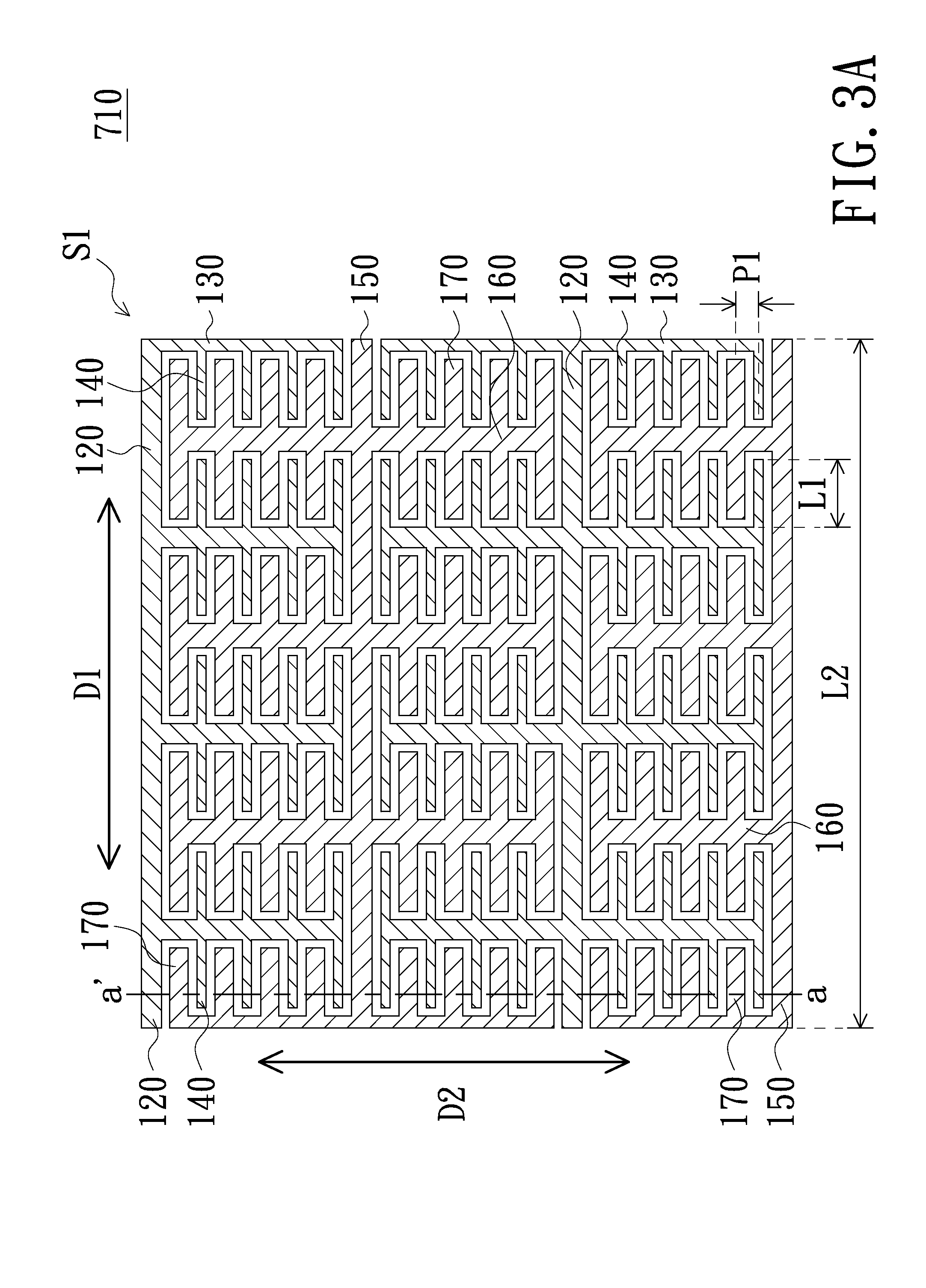
[0021]FIG. 3A is a schematic plan view illustrating a back surface of a back contact solar cell in accordance with an embodiment of the present invention. FIGS. 3B-3C are schematic cross-sectional views taken along line a-a′ in FIG. 3A. The back contact solar cell 710 includes a main body 110, at least one first main busbar electrode 120, at least one first sub-busbar electrode 130, a plurality of first finger electrodes 140, at least one second main busbar electrode 150, at least one second sub-busbar electrode 160 and a plurality of second finger electrodes 170.

[0022]Please be noted that the number, size, scale or dimension of ...


PUM


Abstract

A back contact solar cell includes a first main busbar electrode, a second main busbar electrode, a plurality of first finger electrodes and a plurality of second finger electrodes, all of which are disposed on a back surface of the back contact solar cell and extending along a first direction. The back contact solar cell further includes a first sub-busbar electrode and a second sub-busbar electrode, which are extending along a second direction. The first finger electrodes are electrically connected to an N-type doped region, and the second finger electrodes are electrically connected to a P-type doped region. The first sub-busbar electrode is electrically connected to the first main busbar electrode and the first finger electrodes. The second sub-busbar electrode is electrically connected to the second main busbar electrode and the second finger electrodes.

Description

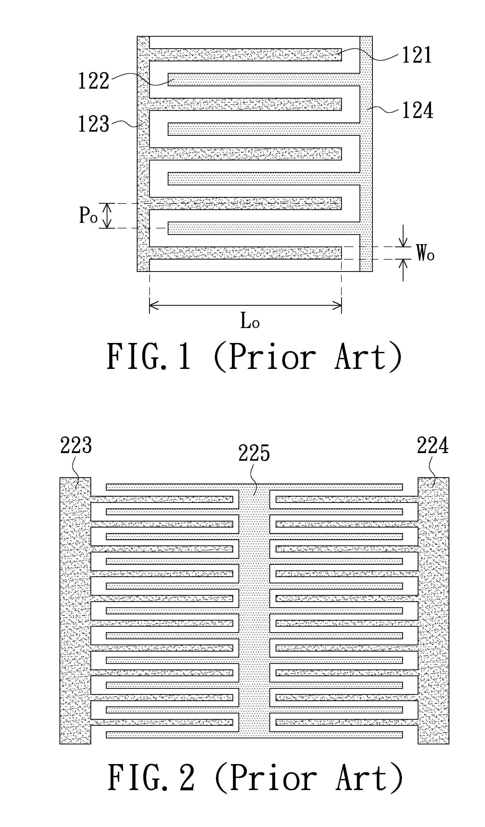
FIELD OF THE INVENTION[0001]The present invention relates to a structure of a solar cell, and more particularly to an electrode configuration of a back contact solar cell.BACKGROUND OF THE INVENTION[0002]In a conventional solar cell, top electrodes are disposed on an upper surface of a substrate, and bottom electrodes are disposed on a lower surface of the substrate. The upper surface is configured for receiving sunlight, but the top electrodes disposed on the upper surface will block incident sunlight and a photoelectric conversion efficiency of the solar cell will be adversely affected. In order to solve the problem, a back contact solar cell is developed wherein both the top electrodes and the bottom electrodes (or said positive electrodes and negative electrodes) are arranged on a back surface opposite to the light receiving surface of the substrate in an interdigitated mode. FIG. 1 is a schematic plan view illustrating a back surface of the conventional back contact solar cell....

Claims


Application Information

Patent Timeline
IPC IPC(8): H01L31/0224
CPCH01L31/022441H01L31/0516Y02E10/50
Inventor LIN, CHIA-LUNGCHENG, YU-TACHEN, CHUAN-CHICHIEN, JUNG-WU
Owner INVENTEC SOLAR ENERGY CORP
Learn More