Ceramic heater, glow plug, method of manufacturing ceramic heater and method of manufacturing glow plug

a ceramic heater and glow plug technology, applied in the direction of heater elements, manufacturing tools, lighting and heating equipment, etc., can solve the problems of cracks and cracks around the protruding protruding, and achieve the effect of suppressing cracks of ceramic heaters

Active Publication Date: 2015-01-15
NGK SPARK PLUG CO LTD
View PDF2 Cites 10 Cited by
  • Summary
  • Abstract
  • Description
  • Claims
  • Application Information

AI Technical Summary

Benefits of technology

[0011]The main advantage of the present invention is that cracking of a ceramic heater is suppressed.
[0012]The present invention has been accompl...

Problems solved by technology

When such protrusions are formed, cracks may be generated around the protrusions.
Accordingly, due to a difference in temperature between perio...

Method used


Image

  • Ceramic heater, glow plug, method of manufacturing ceramic heater and method of manufacturing glow plug
  • Ceramic heater, glow plug, method of manufacturing ceramic heater and method of manufacturing glow plug
  • Ceramic heater, glow plug, method of manufacturing ceramic heater and method of manufacturing glow plug

Examples


embodiment

A. Embodiment

A1. Structure of Glow Plug:

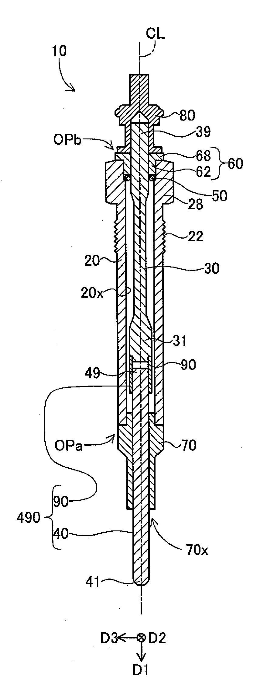
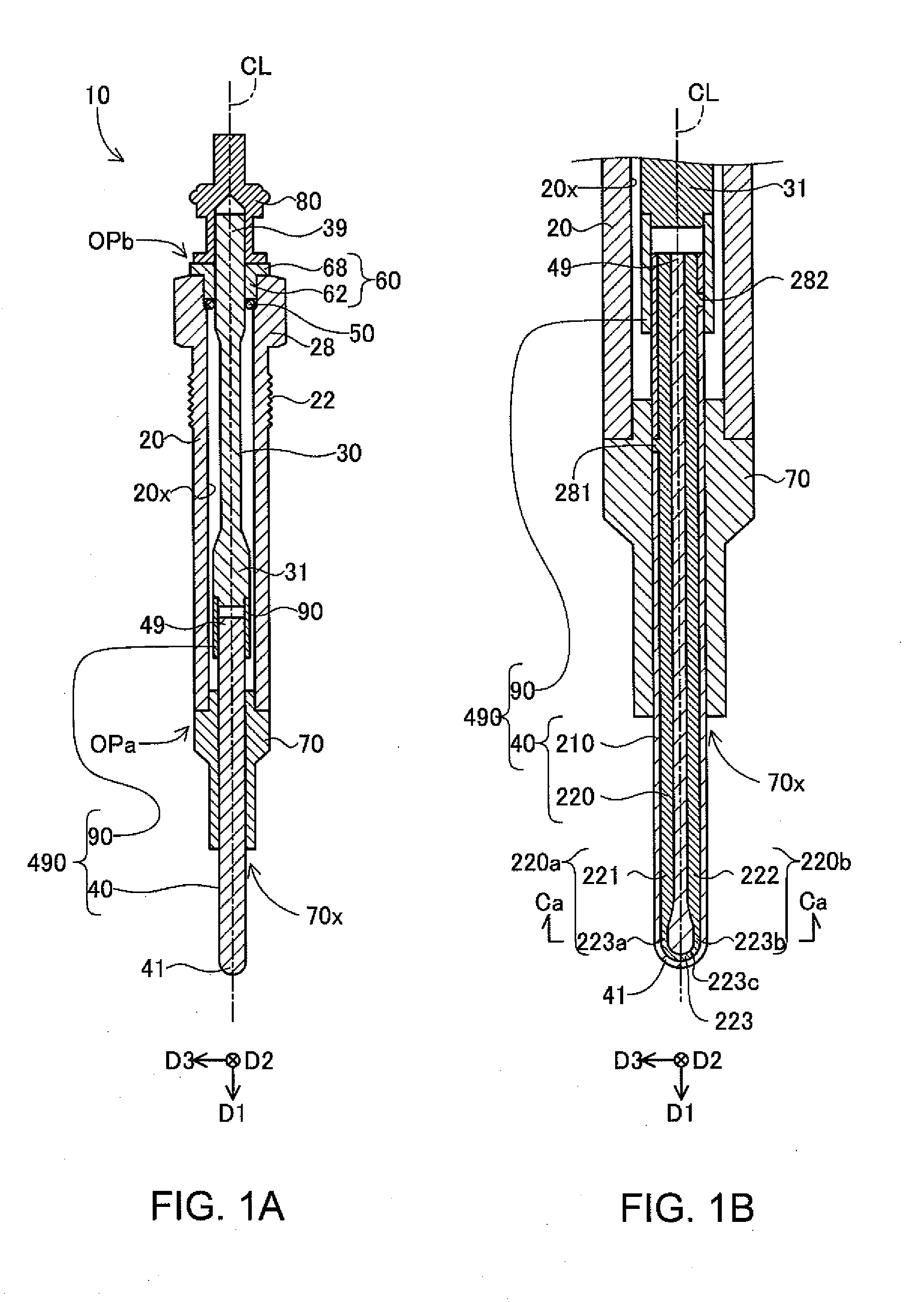
[0055]A mode of the present invention will be described on the basis of an embodiment. FIGS. 1(A) and 1(B) are explanatory views showing a glow plug according to one embodiment of the present invention. The glow plug 10 functions as a heat source for, for example, assisting startup of an unillustrated internal combustion engine (e.g., a diesel engine). FIG. 1(A) is a longitudinal sectional view of the glow plug 10, and FIG. 1(B) is an enlarged sectional view showing a portion of the glow plug 10 (a portion including a ceramic heater 40). A line CL shown in these drawing shows a center axis of the glow plug 10. In the following description, the center axis CL is also referred to as the “axial line CL,” and a direction parallel to the center axis CL is also referred to as the “axial direction.” A first direction D1 in the drawings is a direction parallel to the axial line CL. As will be described later, the ceramic heater 40, which generates hea...


PUM

PropertyMeasurementUnit
Lengthaaaaaaaaaa

Abstract

A ceramic heater wherein in at least one cross section of the ceramic heater orthogonal to the axial direction, a first resistor cross section has no protrusion on a first inner portion of the contour of a first resistor cross section, and has two or more protrusions on a first outer portion of the contour of the first resistor cross section and a method of manufacturing the ceramic heater.

Description

FIELD OF THE INVENTION[0001]The present invention relates to a ceramic heater used for a glow plug or the like.BACKGROUND OF THE INVENTION[0002]Conventionally, a ceramic heater has been utilized for various apparatuses, such as a glow plug. For manufacture of such a ceramic heater, there has been utilized a method of molding a heating element and a ceramic base member through use of molding dies.PRIOR ART DOCUMENT[0003]Patent Document 1: JP 2002-334768 A[0004]Patent Document 2: WO2011 / 052624 A1[0005]Patent Document 3: WO2008 / 123296 A1[0006]Patent Document 4: JP 10-110951 A[0007]Patent Document 5: JP 2005-340034 A[0008]Patent Document 6: JP 2007-265893 A[0009]Patent Document 7: JP 2003-40678 A[0010]However, in the case where molding is performed through use of molding dies, protrusions (also called burrs) may be formed as a result of the molding process. When such protrusions are formed, cracks may be generated around the protrusions. For example, a heating resistor having a generall...

Claims


Application Information

Patent Timeline
IPC IPC(8): H05B3/48F23Q7/00B28B11/00H05B3/18
CPCF23Q2007/004F23Q7/001Y10T29/49083H05B3/48H05B3/18B28B11/00H05B2203/027H05B3/02H05B3/06H05B3/141H05B2203/017
Inventor IKAI, YOSHIHITOSUZUKI, RYOSEKIGUCHI, YUTAKA
Owner NGK SPARK PLUG CO LTD
Why Eureka
Try Eureka