Cable and compensation method for transmitting high speed signal and delivering power

a compensation method and high-speed signal technology, applied in logic circuit coupling/interface arrangement, process and machine control, instruments, etc., can solve the problems of increased length of cable, signal transmission may suffer from attenuation, and drop in transfer voltage, so as to achieve stable and efficient power transmission

Inactive Publication Date: 2015-01-15
SMARTPHY INC
View PDF2 Cites 45 Cited by
  • Summary
  • Abstract
  • Description
  • Claims
  • Application Information

AI Technical Summary

Benefits of technology

[0038]According to an embodiment of this disclosure, a cable and compensating method for high-speed transmission of signals and power are provided.
[0039]The cable and compensating method disclosed herein may compensate for a voltage drop component corresponding to a power line included in the cable, thus allowing for stable and efficient power transmission through the cable.

Problems solved by technology

However, as the distance between a transmitting device and a receiving device increases, the length of the cable increases, and in such case, signals transmitted may suffer from attenuation and drop in the transferred voltage due to the signal transfer characteristics of the cable and voltage drop in the cable.

Method used


Image

  • Cable and compensation method for transmitting high speed signal and delivering power
  • Cable and compensation method for transmitting high speed signal and delivering power
  • Cable and compensation method for transmitting high speed signal and delivering power

Examples


first embodiment

[0102-Arrangement of Voltage Compensator

[0103]The first embodiment disclosed herein may be implemented by some or combinations of the components or steps included in the above-described embodiments or combinations of the embodiments. Hereinafter, description of the duplicates will be skipped for clear expression of the first embodiment disclosed herein.

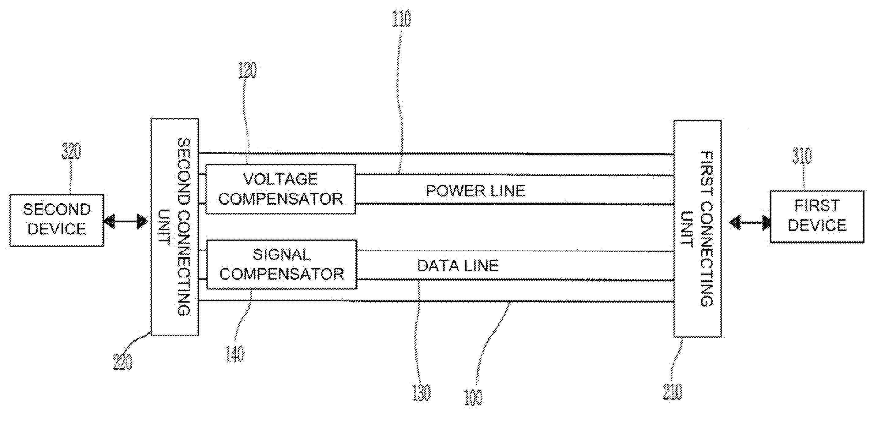
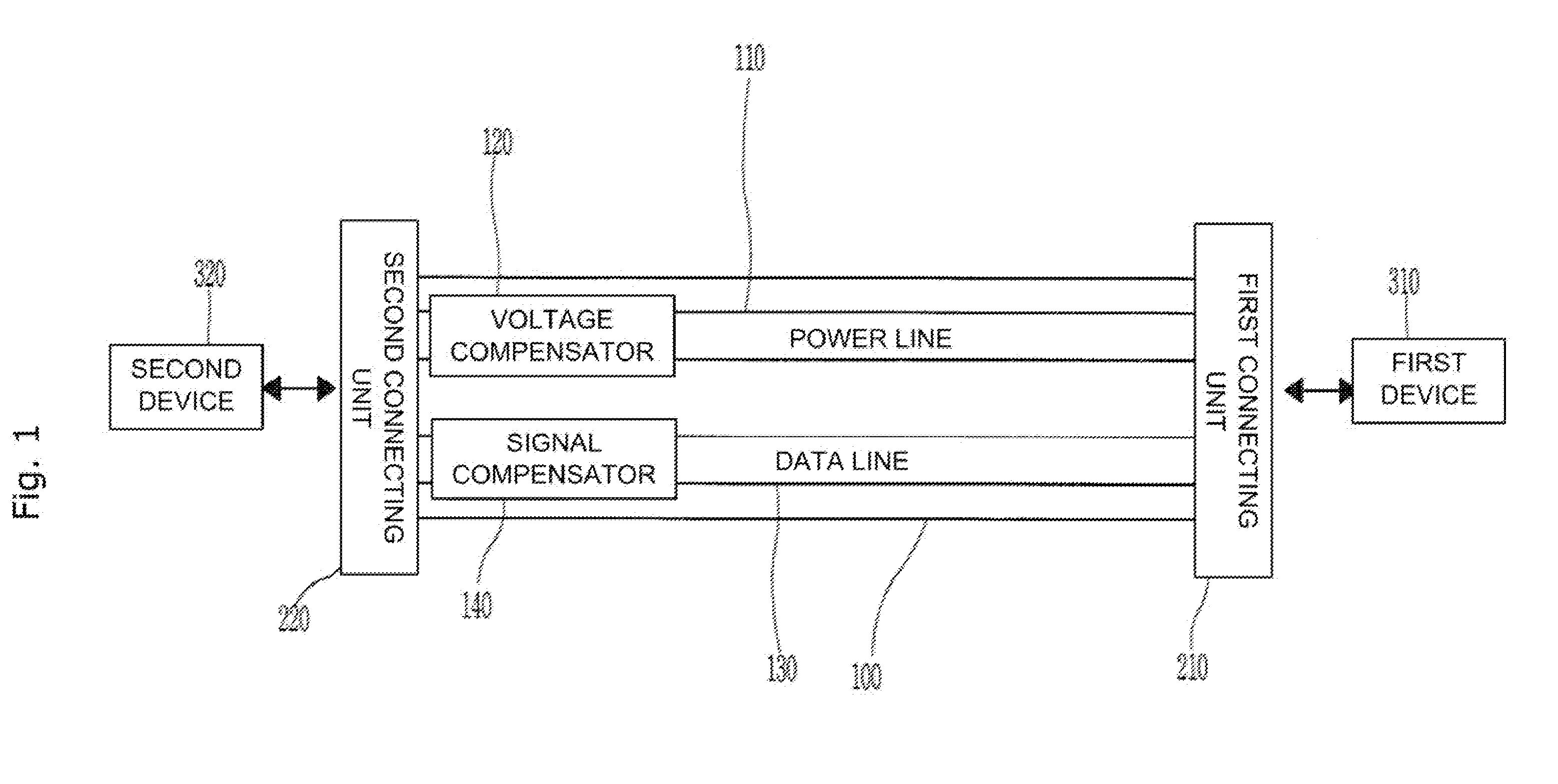
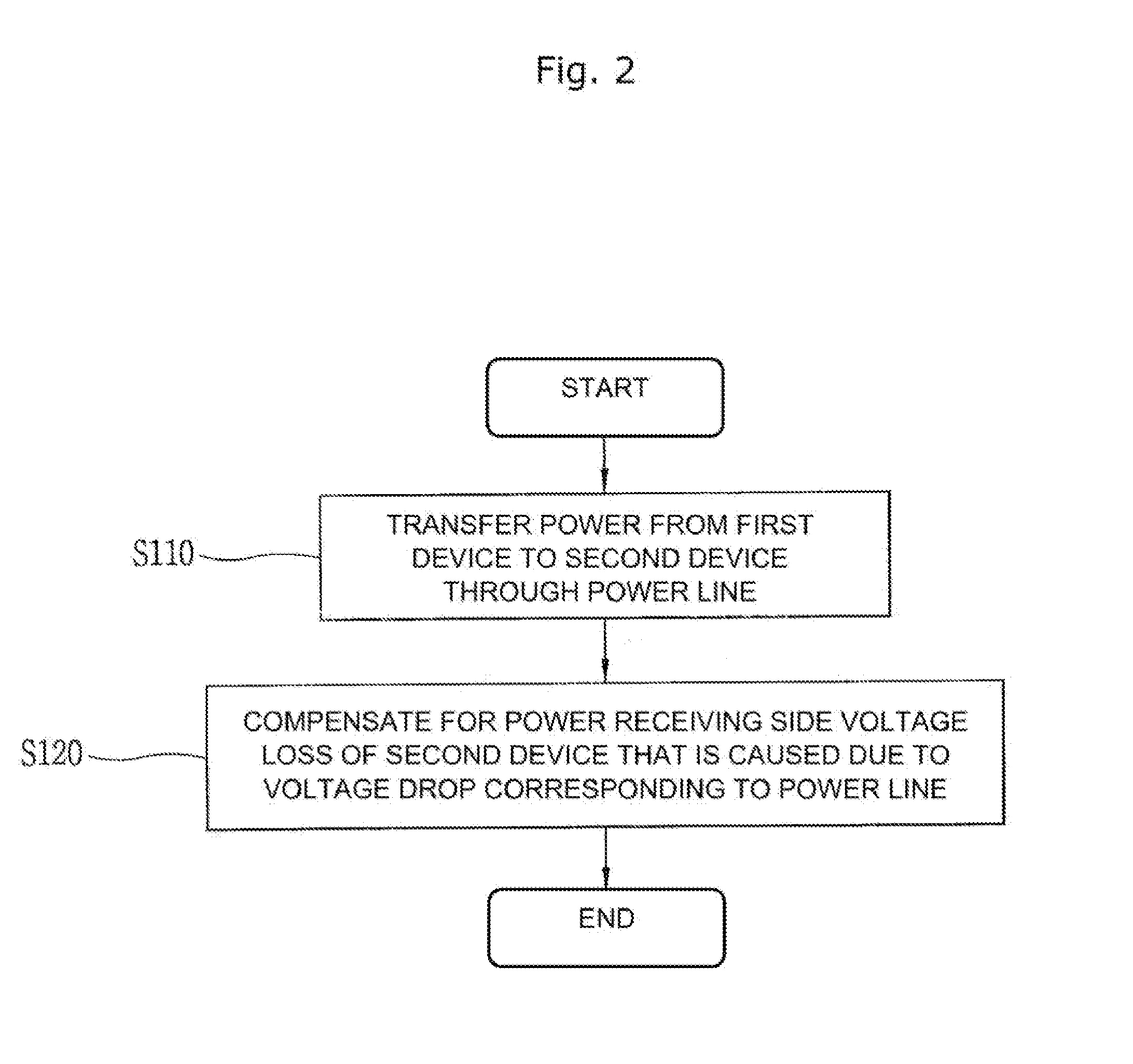
[0104]The cable according to the first embodiment disclosed herein may include a power line transferring power from a first device to a second device and a voltage compensator compensating for a power receiving side voltage loss of the second device that is caused due to a voltage drop corresponding to the power line.

[0105]Further, according to the first embodiment, the voltage compensator may be disposed at a power transmitting side of the first device, a power receiving side of the second device, or a middle position of the power line.

[0106]FIG. 3 is a view illustrating a method of disposing a voltage compensator according to the fi...

second embodiment

[0117-Voltage Compensator Compensating for Voltage Loss that is Caused Due to Voltage Drop

[0118]The second embodiment disclosed herein may be implemented by some or combinations of the components or steps included in the above-described embodiments or combinations of the embodiments. Hereinafter, description of the duplicates will be skipped for clear expression of the second embodiment disclosed herein.

[0119]The cable according to the second embodiment disclosed herein may include a power line transferring power from a first device to a second device and a voltage compensator compensating for a power receiving side voltage loss of the second device that is caused due to a voltage drop corresponding to the power line.

[0120]Further, according to the second embodiment, the voltage compensator may compensate for the power receiving side voltage loss in various ways. For example, the voltage compensator may compensate for the power receiving side voltage loss based on at least one of a ...

third embodiment

[0169-Signal Compensator Compensating for Data Signal Loss

[0170]The third embodiment disclosed herein may be implemented by some or combinations of the components or steps included in the above-described embodiments or combinations of the embodiments. Hereinafter, description of the duplicates will be skipped for clear expression of the third embodiment disclosed herein.

[0171]The cable according to the third embodiment disclosed herein may include a power line transferring power from a first device to a second device and a voltage compensator compensating for a power receiving side voltage loss of the second device that is caused due to a voltage drop corresponding to the power line.

[0172]Further, the cable according to the third embodiment may further a data line transferring a data signal from the second device to the first device and a signal compensator that compensates for the data signal loss generated due to signal transfer characteristics of the data line.

[0173]FIG. 9 is a f...


PUM


Abstract

The present specification provides a cable and a compensation method for transmitting a high speed signal and delivering power. The cable according to one embodiment disclosed in the present specification interconnects a first device and a second device, the cable comprising: a power line for transmitting power from the first device to the second device; and a voltage restorer for restoring voltage loss of the power receiving side of the second device generated based on the voltage drop relevant to the power line.

Description

CROSS-REFERENCE TO RELATED APPLICATIONS[0001]This application is a U.S. national stage application under 35 U.S.C. §371 (c) of PCT Application No. PCT / KR2012 / 002207, entitled “CABLE AND COMPENSATION METHOD FOR TRANSMITTING HIGH SPEED SIGNAL AND DELIVERING POWER,” filed on Mar. 27, 2012, the disclosure of which is incorporated by reference herein in its entirety.TECHNICAL FIELD[0002]This disclosure relates to a cable and a compensating method for high-speed signal transmission and power transfer.DISCUSSION OF RELATED ART[0003]A recent increase in demand for electronics having higher resolution and definition has been drastically changing electronics industry. In particular, as display panels such as liquid crystal displays (LCDs), plasma display panels (PDPs), and high-definition televisions (HDTVs) develop, the interface for transmitting high-volume image data plays a critical role.[0004]Interface standards have been created and used in order to apply interfaces to various display p...

Claims


Application Information

Patent Timeline
Patent Type & Authority Applications(United States)
IPC IPC(8): G05F5/00H03H17/02
CPCH03H17/0248G05F5/00H04L25/0276H04L25/03146H04L25/0282H03K19/0175
Inventor KIM, OOK
Owner SMARTPHY INC
Why Eureka
Try Eureka