Cable for electrical and optical transmission

a technology for optical transmission and cables, applied in the direction of insulated conductors/cables, cables, cables, etc., can solve the problems of difficult pulling apart and soldering, weaving can be difficult to manipulate, and the cable may not be able to convey signals at these higher data rates, so as to achieve easy manipulation during manufacturing, less likely to be damaged, and good tensile strength

Inactive Publication Date: 2012-04-05
APPLE INC
View PDF37 Cites 42 Cited by
  • Summary
  • Abstract
  • Description
  • Claims
  • Application Information

AI Technical Summary

Benefits of technology

[0007]Accordingly, embodiments of the present invention may provide circuits, methods, and apparatus that provide cables capable of high-speed transmission while remaining compatible with legacy signals. Embodiments of the present invention may have shielding that may be easily manipulated during manufacturing. Embodiments of the present invention may have good tensile strength, and may be less likely to be damaged by twisting and bending that may occur during use.

Problems solved by technology

Unfortunately, these cables may not be capable of conveying signals at these higher data rates.
But this weave can be difficult to manipulate during cable manufacturing.
Since the braiding is woven, it may be difficult to pull apart and solder.
One difficulty encountered with cables is that they may be pulled, stretched, twisted, or bent.
This may damage or break either the cable or one or more internal conductors.

Method used


Image

  • Cable for electrical and optical transmission
  • Cable for electrical and optical transmission
  • Cable for electrical and optical transmission

Examples


Embodiment Construction

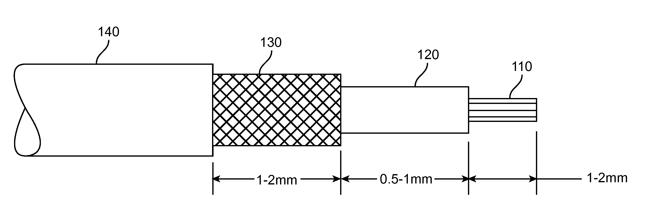
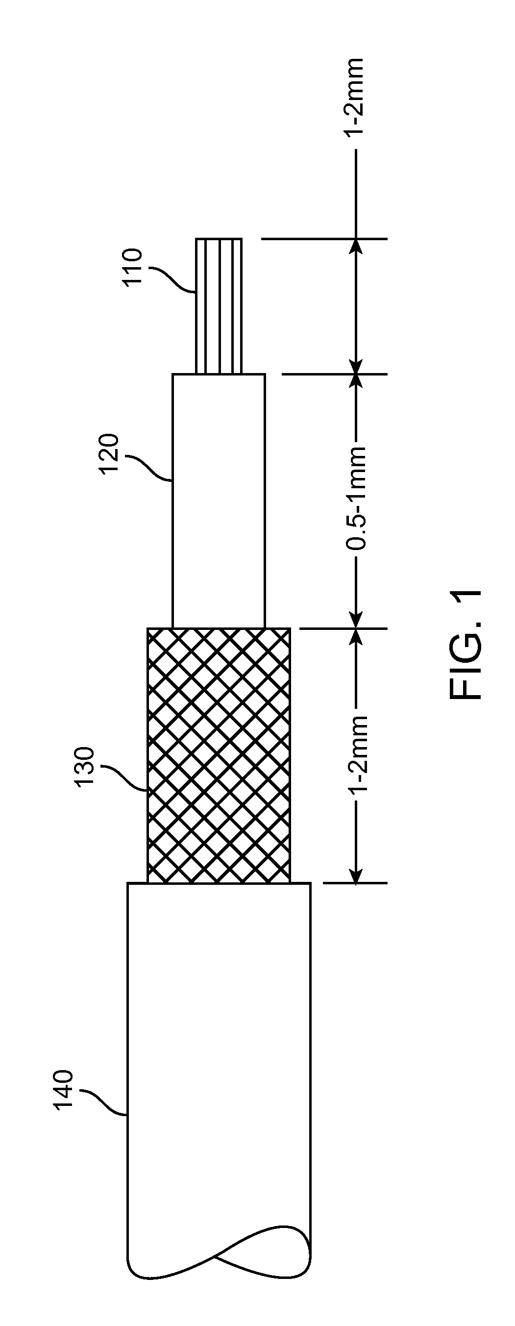
[0022]FIG. 1 illustrates various layers of a high-speed cable according to an embodiment of the present invention. This cable includes center conductors 110, dielectric 120, shield 130, and jacket 140. Center conductors 110 may include single conductors, coaxial conductors, or pairs of conductors, such as twinaxial, twisted-pair, shielded twisted pair, or other pairs of conductors. The conductors may convey power, data, status or other information. The conductors may be single wires or multiple strands of wires. In some embodiments of the present invention, one or more conductors may be formed of a group of strands of wires, where each wire is coated with a layer of material to provide spatial separation among the strands. This separation aids in limiting skin effects and thus limits skin effects. This layer of material may be enamel or other material. The wires may be arranged as a Litz wire. Each of these various conductors may be formed of copper, aluminum, or other conductive ma...


PUM

PropertyMeasurementUnit
angleaaaaaaaaaa
poweraaaaaaaaaa
angleaaaaaaaaaa

Abstract

Circuits, methods, and apparatus that provide cables capable of high-speed transmission while remaining compatible with legacy signals. Other examples may have shielding that may be easily manipulated during manufacturing, they may have good tensile strength, and they may be less likely to be damaged by twisting and bending that may occur during use.

Description

BACKGROUND[0001]The amount of data transferred between electronic devices has grown tremendously the last few years. Large amounts of audio, video, text, and other types of data content, are now regularly transferred among computers, media devices, such as handheld media devices, displays, storage devices, and other types of electronic devices. Since it is often desirable to transfer this data rapidly, the data rates of these transfers have substantially increased.[0002]This data is often transferred over cables. Unfortunately, these cables may not be capable of conveying signals at these higher data rates. But while improved cables capable of operating at higher speeds are desirable, it is often useful to be backward compatible with older or legacy technologies. Accordingly, it is desirable to have cables that can operate at these higher data rates while remaining compatible with legacy technologies.[0003]One feature common to cables is the use of a braided shield. This shield may ...

Claims


Application Information

Patent Timeline
Patent Type & Authority Applications(United States)
IPC IPC(8): H01B7/00G02B6/04
CPCG02B6/4416G02B6/4432H01B11/1041H01B13/14H01B13/02H01B13/0016H01B13/06H01B11/22
Inventor KIM, MIN CHULDUPERRON, VINCE
Owner APPLE INC
Why Eureka
Try Eureka