Dynamic mixed-mode current decay apparatus and methods

a mixed-mode current and decay apparatus technology, applied in the direction of electrical apparatus, control system, dynamo-electric converter control, etc., can solve the problems of slow decay mode, limited micro-stepping resolution, and limited micro-stepping resolution for a given stepper motor configuration, so as to reduce the variation of winding current

Active Publication Date: 2015-01-15
TEXAS INSTR INC
View PDF5 Cites 12 Cited by
  • Summary
  • Abstract
  • Description
  • Claims
  • Application Information

AI Technical Summary

Benefits of technology

[0024]The magnitude of the DAC analog output corresponds to DAC code presented at digital inputs to the DAC and/or latched into an input section of the DAC. The selected level of current in the motor winding corresponding to a particular DAC code is referred to herein as the current regulation set-point “ITRIP.” The selected period of time corres

Problems solved by technology

Micro-stepping resolution, the number of steps in an electrical 360 degree revolution, is limited by the accuracy with which each motor winding current level can be regulated during the constant current portion of each step.
The inability of conventional decay modes to precisely regulate average current level and ripple in the windings at a particular step may significantly limit micro-stepping resolution for a given stepper motor configuration.
A potential problem exists with slow decay mode, particularly for smaller regulated currents.
This problem may impose a lower limit on the magnitude of current that may be finely regulated and thus on the driver DAC step size and resolution.
A potential problem with fast decay mode is that th

Method used


Image

  • Dynamic mixed-mode current decay apparatus and methods
  • Dynamic mixed-mode current decay apparatus and methods
  • Dynamic mixed-mode current decay apparatus and methods

Examples


Embodiment Construction

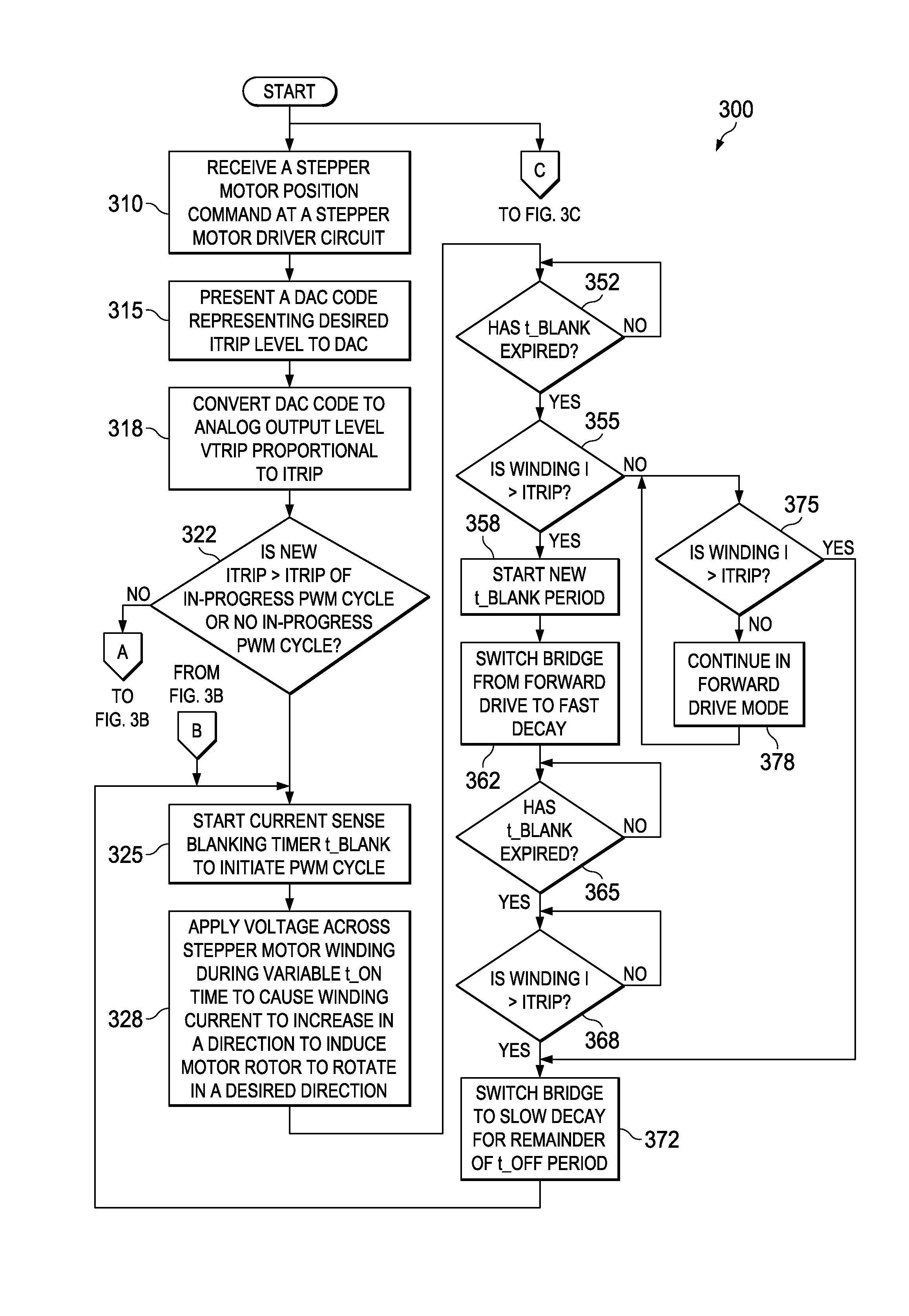
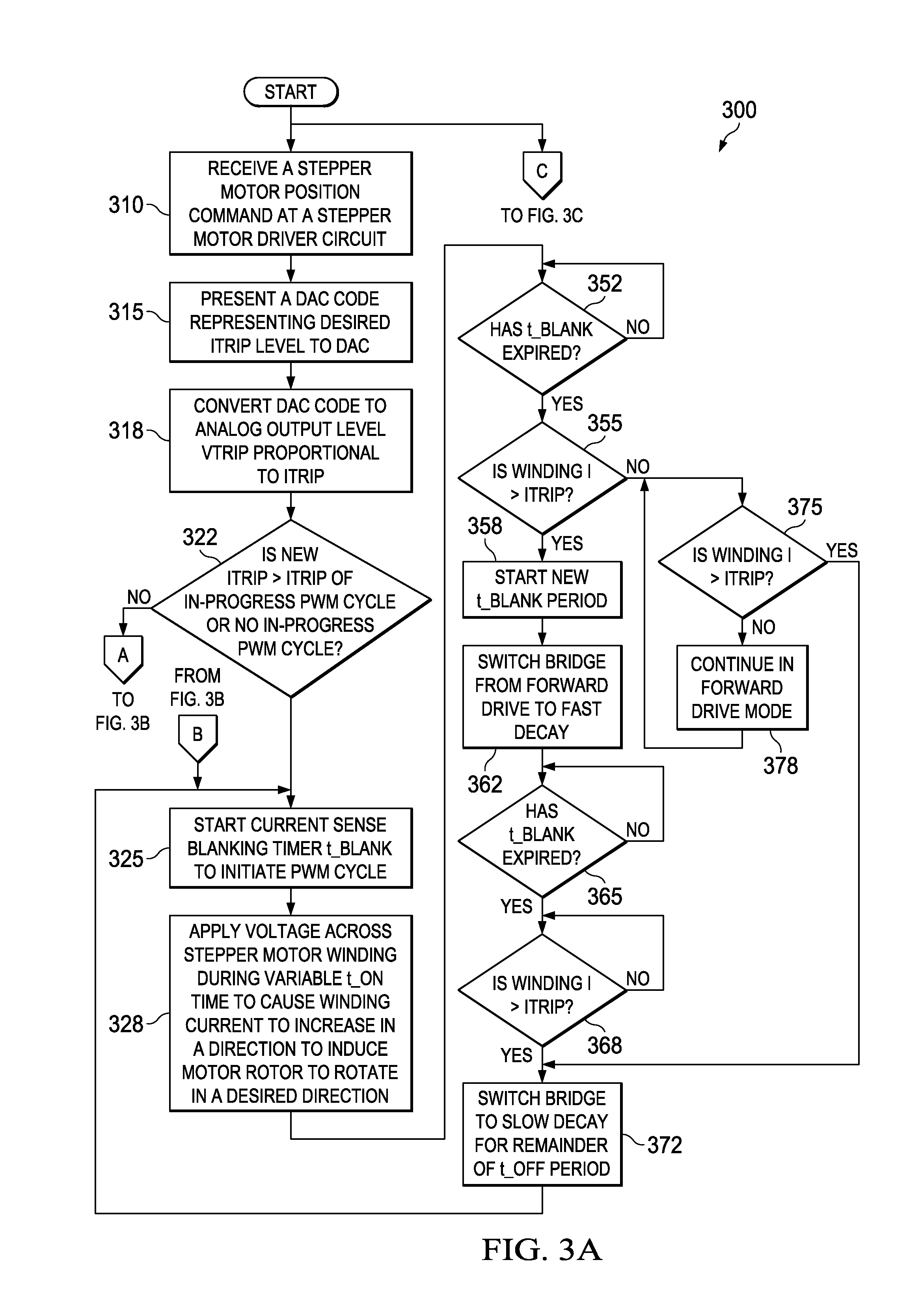
[0028]FIGS. 3A-3C are a flow diagram illustrating a method 300 of stepper motor winding current regulation according to various example activities associated with the invention. Some or all of the activities of the method 300 may be carried out by embodiments of an apparatus described further below or other apparatus. The method 300 may include generating a sequence of DAC codes at an indexer. The sequence of DAC codes corresponds to a desired shape of a stepper motor winding current waveform to be used to move a rotor of the stepper motor from a current position to a new position. The method 300 may also include sequentially presenting the sequence of DAC codes to one or more DAC inputs. The portion of the method 300 described below focuses on activities associated with generating PWM cycles to regulate winding current corresponding to a particular DAC code. The method 300 as described below also includes responding to changes in regulation set-point resulting from a transition fro...


PUM


Abstract

Stepper motor winding current regulation methods and apparatus continuously and bi-directionally sense winding current to determine both the magnitude of the winding current and the slope of a waveform representing the winding current. The magnitude and slope information is used to more precisely control periods of current rise and characteristics of fast and slow current decay during pulse-width modulation (“PWM”) regulation cycles. Winding current rise and decay shaping is based upon the sensed magnitude of the winding current, the magnitude of the winding current regulation set-point ITRIP, whether the sensed winding current is greater than or less than ITRIP at a selected sampling time, whether the sensed winding current is increasing or decreasing when a waveform of the sensed winding current crosses over ITRIP, and whether or not the magnitude of ITRIP changes during a PWM cycle in response to a receipt of a subsequent DAC code.

Description

PRIORITY CLAIM[0001]This application claims the benefit of priority under 35 U.S.C. §119(e) to U.S. Provisional Patent Application Ser. No. 61 / 844,759 titled “A Novel Dynamic Mixed Decay Approach Using Continuous Bi-directional Current Sensing for Current Regulation In Stepper Motors,” filed on Jul. 10, 2013 and incorporated herein by reference in its entirety.TECHNICAL FIELD[0002]Structures and methods described herein relate to electromagnetic current regulation in rotating machinery, including control of current decay in a stepper motor winding.BACKGROUND INFORMATION[0003]In stepper motors, motor position is controlled by regulating electrical current in each motor winding. Different stepper motor designs may have different numbers of windings, with the current waveform in each winding leading or lagging current waveforms associated with the other windings. For purposes of this disclosure, current regulation in a single winding is referred to as an example of the current regulati...

Claims


Application Information

Patent Timeline
IPC IPC(8): H02P8/32
CPCH02P8/32H02P8/12
Inventor JAIN, ANUJMARASCUTTI, MARIOQU, WENCHAOBUTENHOFF, MICHAEL EDWIN
Owner TEXAS INSTR INC
Why Eureka
Try Eureka