Test Probe Coated with Conductive Elastomer for Testing of Backdrilled Plated Through Holes in Printed Circuit Board Assembly

a technology of conductive elastomer and test probe, which is applied in the field of integrated circuit devices, can solve the problems of adding to the cost and complexity of the manufacturing process and the resultant products, and achieve the effect of promoting the adhesion of the elastomer test probe tip

Active Publication Date: 2015-01-15
GLOBALFOUNDRIES US INC
View PDF8 Cites 40 Cited by
  • Summary
  • Abstract
  • Description
  • Claims
  • Application Information

AI Technical Summary

Benefits of technology

[0007]In accordance with various embodiments, an electrical device is provided for probing signal information on a back-drilled plated through hole connector formed in a printed circuit board. The disclosed electrical device includes a conductive probe body on which is formed an elastomer test probe tip. The conductive probe body may include a distal tip region extending a predetermined minimum coverage length (LTIP) that is controlled to be longer than a recess depth dimension (DPL) for a recessed plating layer formed in a back-drilled plated through hole connector to be probed. In selected embodiments, the distal tip region of the conductive probe body has a surface finish (e.g., abraded or slotted) that is disposed to promote adhesion of the elastomer test probe tip. The disclosed elastomer test probe tip is formed around the distal tip region of the conductive probe body and has a total tip width (WTIP) that is controlled to be compressed when inserted into the recessed plating layer formed in a back-drilled plated through hole connector to be probed, thereby establishing a conductive path between the conductive probe body and the recessed plating layer. In selected embodiments, the total tip width (WTIP) of the elastomer test probe tip is controlled to be smaller than a first width mea

Problems solved by technology

While there are a variety of PTH via structure fabrication techniques that are well known and widely employed, different fabrication techniques that use different processing steps can form different t

Method used


Image

  • Test Probe Coated with Conductive Elastomer for Testing of Backdrilled Plated Through Holes in Printed Circuit Board Assembly
  • Test Probe Coated with Conductive Elastomer for Testing of Backdrilled Plated Through Holes in Printed Circuit Board Assembly
  • Test Probe Coated with Conductive Elastomer for Testing of Backdrilled Plated Through Holes in Printed Circuit Board Assembly

Examples


Embodiment Construction

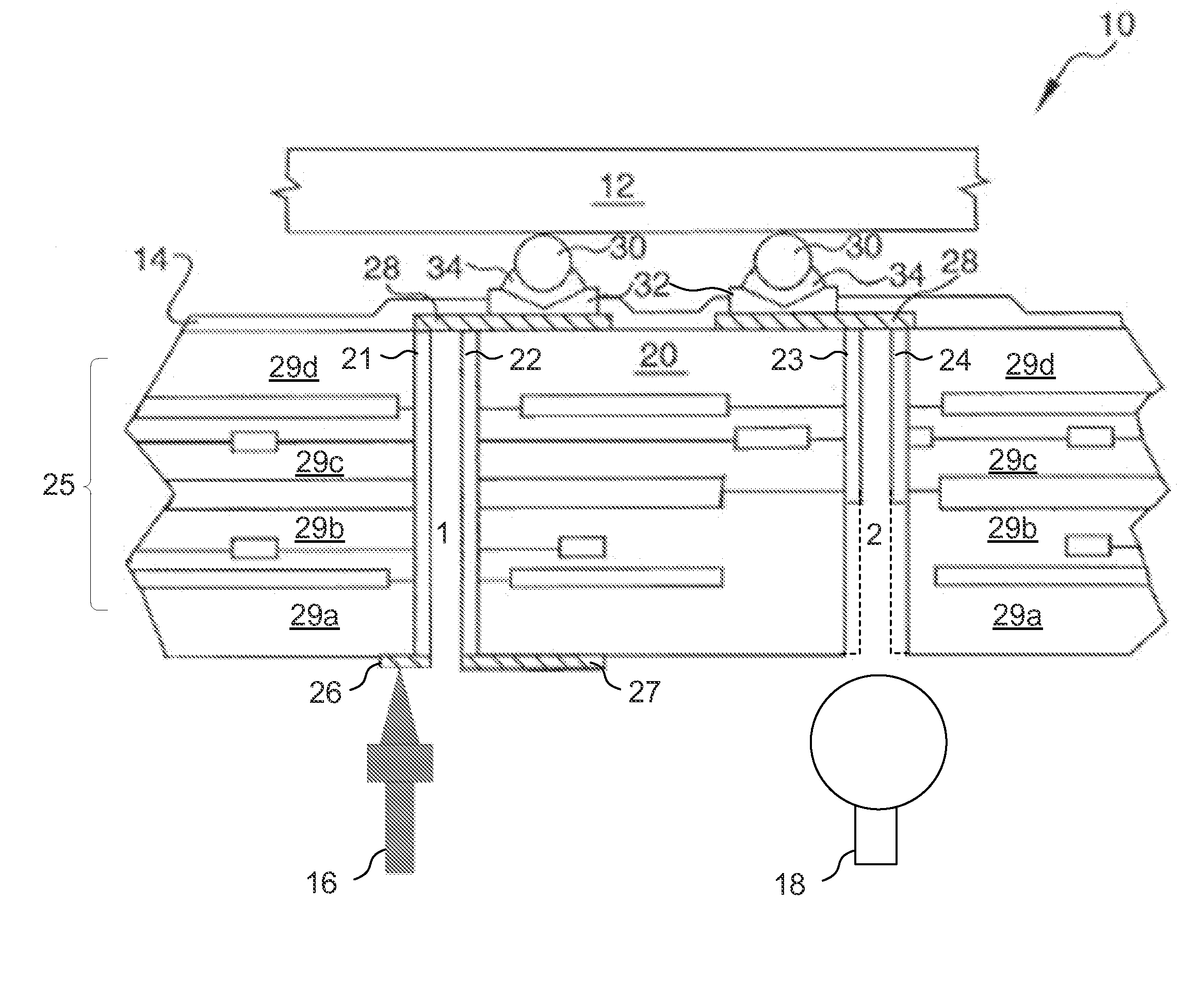
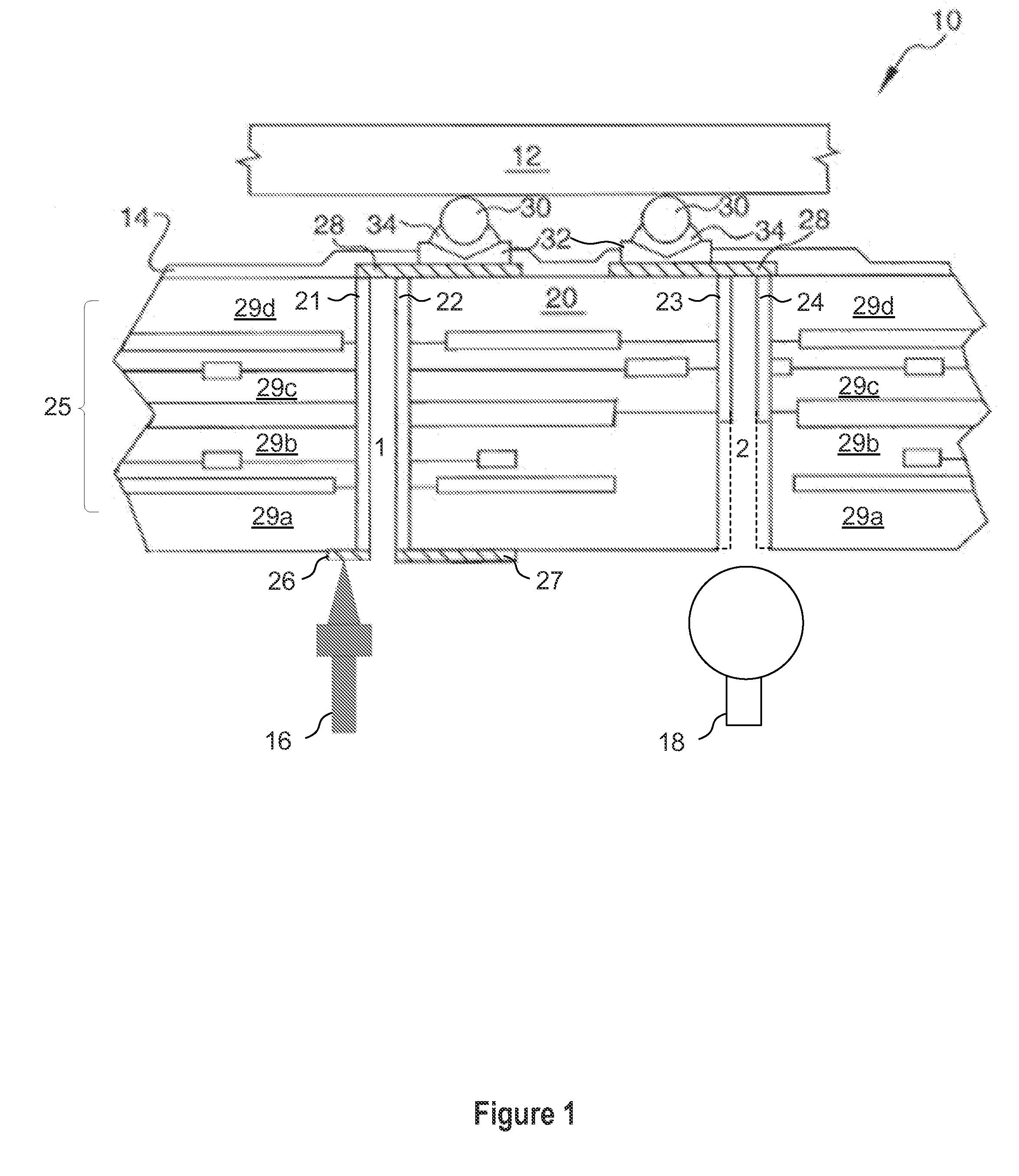
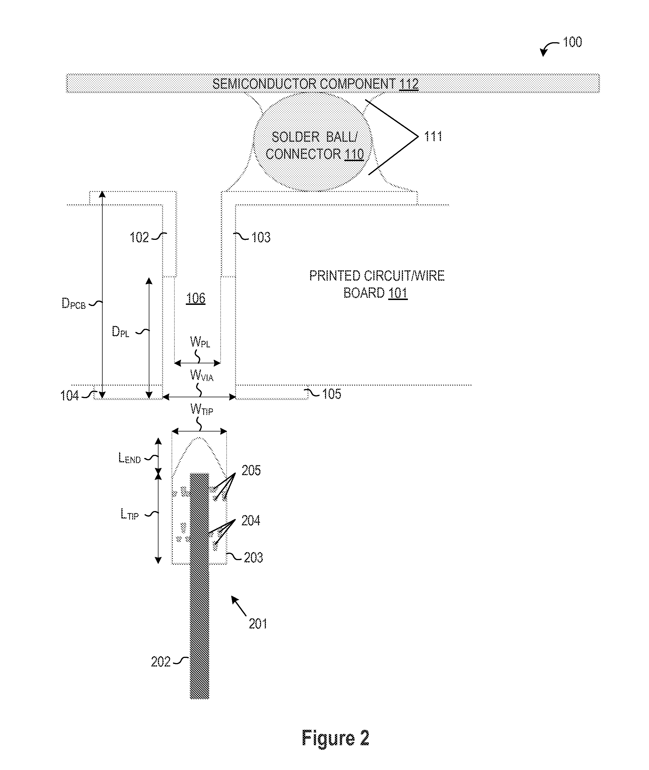
[0015]A high performance test probe having a conductive elastomer tip and associated methodology of fabrication and / or operation are described for testing printed circuit board assemblies having back-drilled plated through holes. In selected embodiments, a test probe includes a flexible or elastic tip structure having predetermined geometric shape dimensions and conductive properties that are suitable for insertion into a back-drilled plated through hole to make electrical contact with back-drilled plating layer(s) in the plated through hole. The elastic tip structure may be formed by spray coating or molding a conductive elastomer material, such as a metal impregnated polymer, on the tip or distal end region of a probe. In selected embodiments, the elastic tip structure may be formed with a chemically bonded conductive or non-conductive polymer matrix containing conductive particles which are positioned and dispersed throughout the polymer matrix to provide a conductive path from t...


PUM


Abstract

A test probe is provided for probing signal information on a back-drilled plated through hole connector formed in a printed circuit board, where the test probe includes a conductive probe body with a distal tip region extending a predetermined minimum coverage length (LTIP) that is longer than a recess depth dimension (DPL) for a recessed plating layer formed in the back-drilled plated through hole connector with an elastomer test probe tip formed around the distal tip region and having a total tip width (WTIP) which is compressed when inserted into the recessed plating layer formed in a back-drilled plated through hole connector, thereby establishing a conductive path between the conductive probe body and the recessed plating layer.

Description

BACKGROUND[0001]1. Field of the Invention[0002]The present invention relates in general to integrated circuits. In one aspect, the present invention relates to a test probe apparatus for integrated circuit devices and methods of use thereof.[0003]2. Description of the Related Art[0004]In the fabrication of high performance electronic or electrical devices and circuits, integrated circuit components may be mounted onto a printed circuit or wiring boards by using plated through holes (PTH) via structures formed in the boards to provide power and / or signal conductors through the boards. Such PTH via structures may be formed by drilling or selectively etching holes in the board which are then coated or plated with one or more metal layers (e.g., copper) to form conductive paths and contact areas on the boards, devices and the like. While there are a variety of PTH via structure fabrication techniques that are well known and widely employed, different fabrication techniques that use diff...

Claims


Application Information

Patent Timeline
IPC IPC(8): G01R1/067G01R31/28
CPCG01R1/06716G01R31/2801G01R1/06755G01R1/06738G01R31/2808
Inventor MA, WAI M.
Owner GLOBALFOUNDRIES US INC
Why Eureka
Try Eureka