Linear actuator and groove fashioning method for linear actuator

Active Publication Date: 2015-01-15
KYB CORP
View PDF11 Cites 4 Cited by
  • Summary
  • Abstract
  • Description
  • Claims
  • Application Information

AI Technical Summary

Benefits of technology

[0004]An object of the present invention is to provide a linear actuator and a method of fashioning a g

Problems solved by technology

Therefore, air resistance in the gap during expansion and contraction of the linear actuator is comparative

Method used


Image

  • Linear actuator and groove fashioning method for linear actuator
  • Linear actuator and groove fashioning method for linear actuator
  • Linear actuator and groove fashioning method for linear actuator

Examples


Example

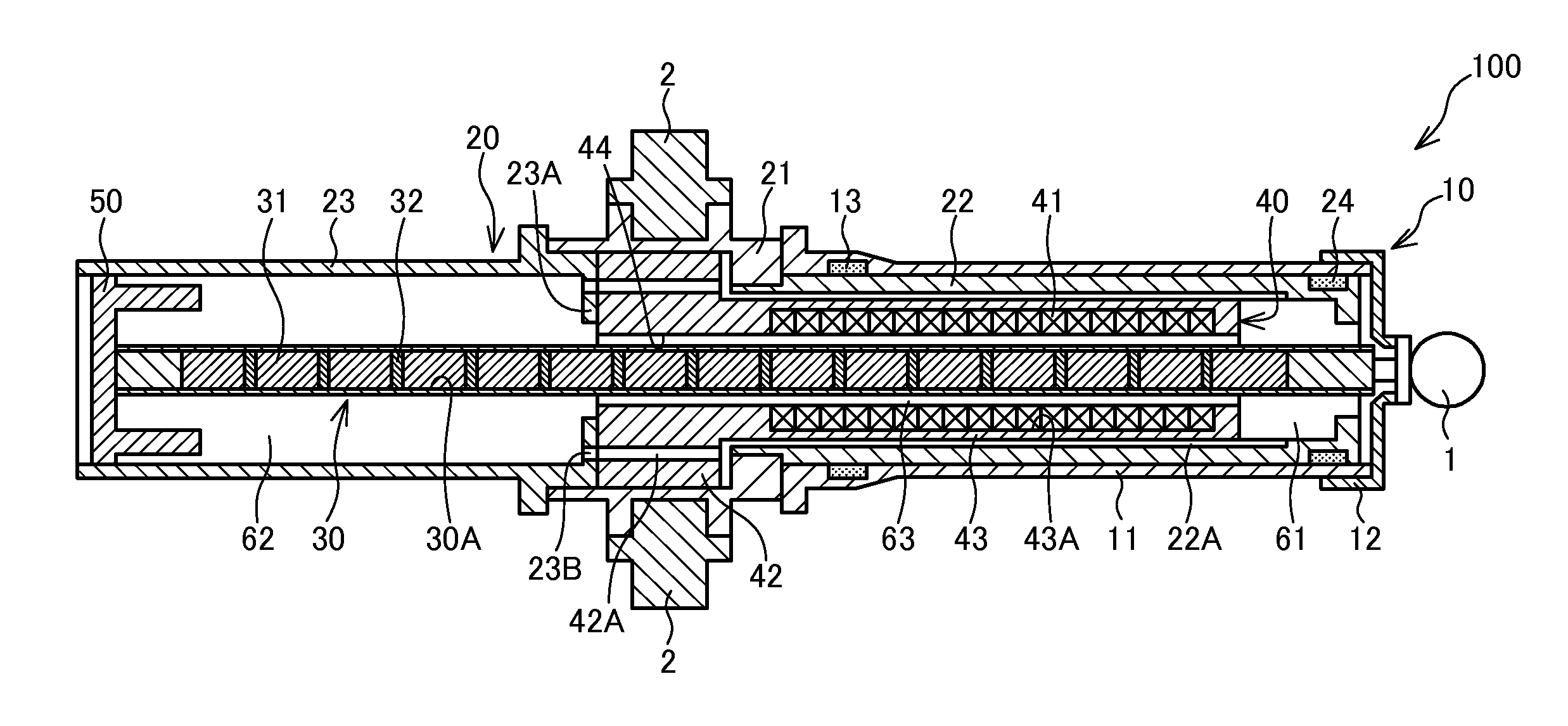
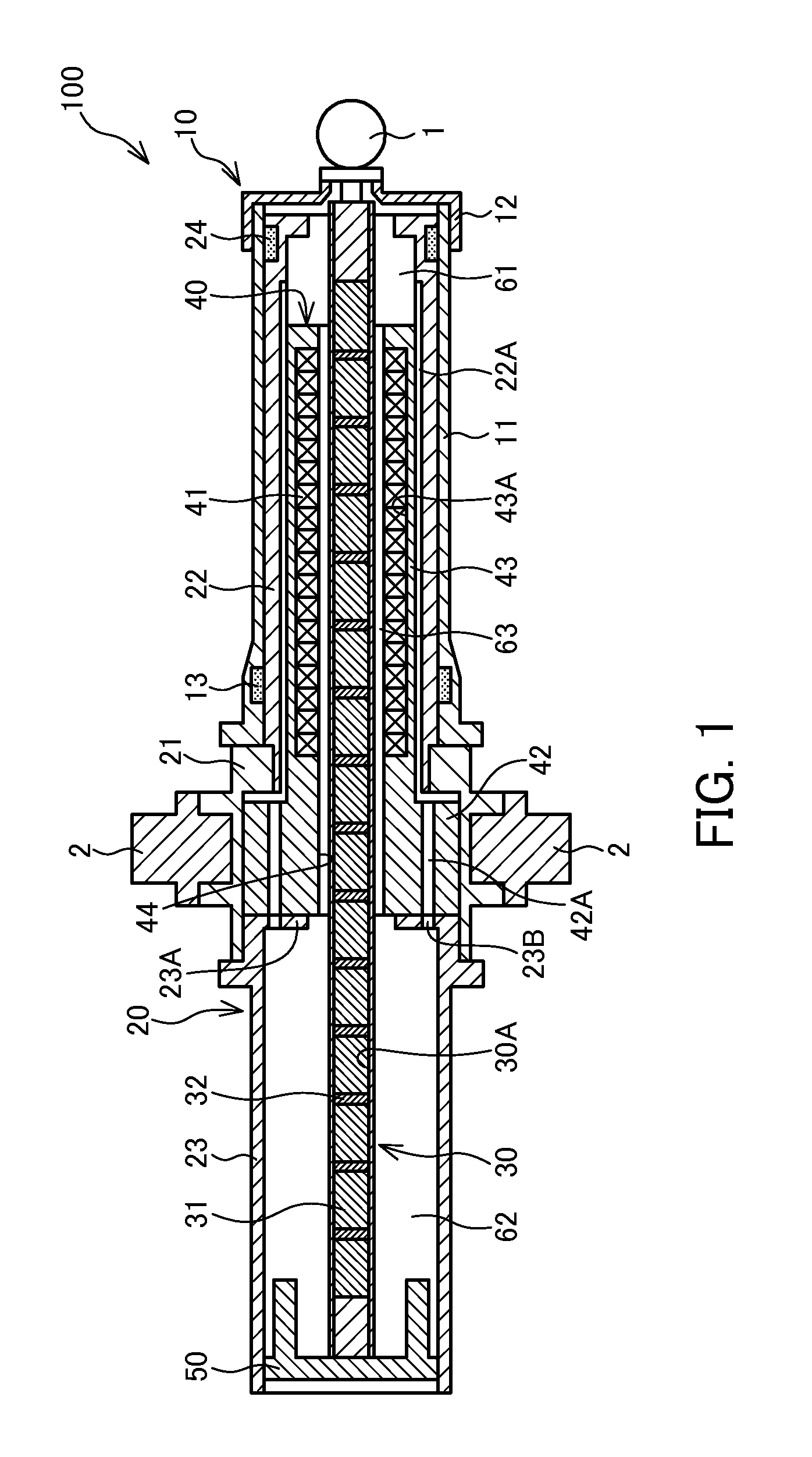
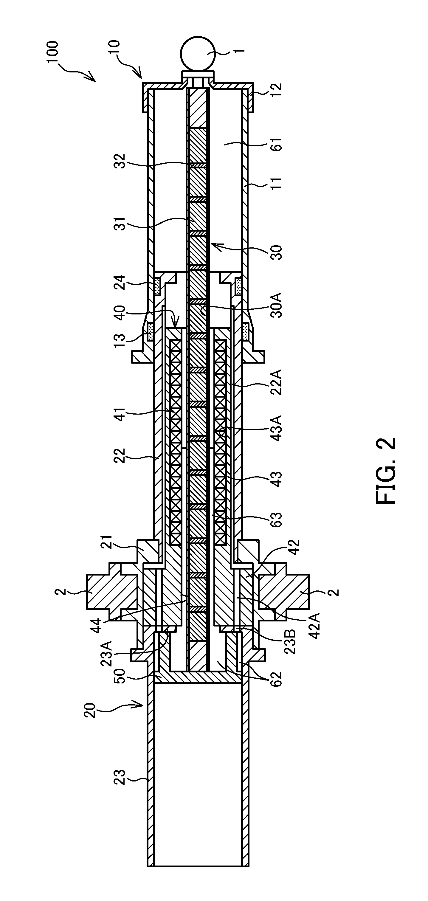
[0010]Referring to FIGS. 1 and 2, a linear actuator 100 according to an embodiment will be described.

[0011]The linear actuator 100 is used as a vibration damping actuator that suppresses vibration of an automobile, a railway vehicle, an architectural structure, or the like.

[0012]The linear actuator 100 includes a first tube 10, a second tube 20 inserted into the first tube 10 to be free to slide, a rod 30 that is fixed to an end portion of the first tube 10 and holds permanent magnets 31, and a coil holder 40 that is provided so as to be fitted into the second tube 20, and holds coils 41 that oppose the permanent magnets 31. The linear actuator 100 is disposed between two members that move relative to each other via a connecting portion 1 provided on the first tube 10 and a connecting shaft 2 provided on the second tube 20.

[0013]In the linear actuator 100, a thrust (an electromagnetic force) for driving the rod 30 in an axial direction is generated in accordance with a current flowi...


PUM

PropertyMeasurementUnit
Diameteraaaaaaaaaa

Abstract

A linear actuator includes a first tube, a second tube inserted into the first tube to be free to slide, a rod fixed at one end of the rod to the first tube, a rod guide provided on the other end of the rod so as to slide relative to the second tube, a plurality of permanent magnets held by the rod, a holder that is fitted into the second tube and holds a plurality of coils, a first chamber defined between one end of the holder and an end portion of the first tube, and a second chamber defined between the other end of the holder and the rod guide. An insertion hole which connects the first chamber to the second chamber and through which the rod passes is formed in the holder. A connecting groove that connects the first chamber to the second chamber is formed in the second tube to extend in an axial direction.

Description

TECHNICAL FIELD [0001]The present invention relates to a linear actuator that expands and contracts in an axial direction, and a method of fashioning a groove in the linear actuator.BACKGROUND ART [0002]JP2004-357464A discloses a linear actuator in which a first tube and a second tube undergo relative displacement in an axial direction on the basis of electromagnetic force generated between permanent magnets provided on the first tube and coils provided on the second tube.SUMMARY OF INVENTION [0003]The linear actuator described in JP2004-357464A is configured such that a space defined on an end portion side of the first tube and a space defined on an end portion side of the second tube communicate with each other only through an extremely small gap between the permanent magnets and the coils arranged in the axial direction. Therefore, air resistance in the gap during expansion and contraction of the linear actuator is comparatively large, and as a result, smooth expansion and contra...

Claims


Application Information

Patent Timeline
IPC IPC(8): H01F7/16
CPCH01F7/1615Y10T82/10H02K41/031B60G2202/422B60G2202/44B60G2600/24H02K2205/12F16F15/03
Inventor SATOU, KOUSUKEKAKIUCHI, TAKASHI
Owner KYB CORP
Why Eureka
Try Eureka