
Visible light communication device, lighting fixture including the same, and lighting system

Active Publication Date: 2015-01-15
PANASONIC CORP
View PDF17 Cites 27 Cited by
  • Summary
  • Abstract
  • Description
  • Claims
  • Application Information

AI Technical Summary

Benefits of technology

The invention aims to provide a visible light communication device that can increase the likelihood of a receiving terminal successfully receiving a communication signal even when receiving light from multiple lighting fixtures at the same time. The device has a simplified structure and is easy to use, which makes it ideal for use in lighting systems. The technical effects of the invention include better reliability and efficiency in communication, improved overall lighting system performance, and simplified user experience.

Problems solved by technology

Hence, a special device such as an infrared communication device is unnecessary.
However, as for a lighting fixture including the illuminating light communication device of the background art, the following undesired situation may occur.
Namely, in a case where a plurality of lighting fixtures are installed so as to illuminate a large space such as an underground mall for example, when rays of illuminating light from the plurality of lighting fixtures overlap each other, such rays of illuminating light interfere with each other, and therefore a receiving terminal such as a mobile phone fails to successfully receive the communication signal.
However, according to this proposal, it is troublesome to construct the system when the lighting fixtures are situated in places where connection of the signal lines is difficult.
Moreover, the system is not available for the lighting fixtures which are devoid of components to be connected to the signal lines.
Additionally, according to this system, it is necessary to add the signal lines to provide the synchronization signals to the illuminating light communication devices, and therefore the installation of the system is troublesome and also it is difficult to install the system especially in large-scale premises.

Method used


Image

  • Visible light communication device, lighting fixture including the same, and lighting system
  • Visible light communication device, lighting fixture including the same, and lighting system
  • Visible light communication device, lighting fixture including the same, and lighting system

Examples


Embodiment Construction

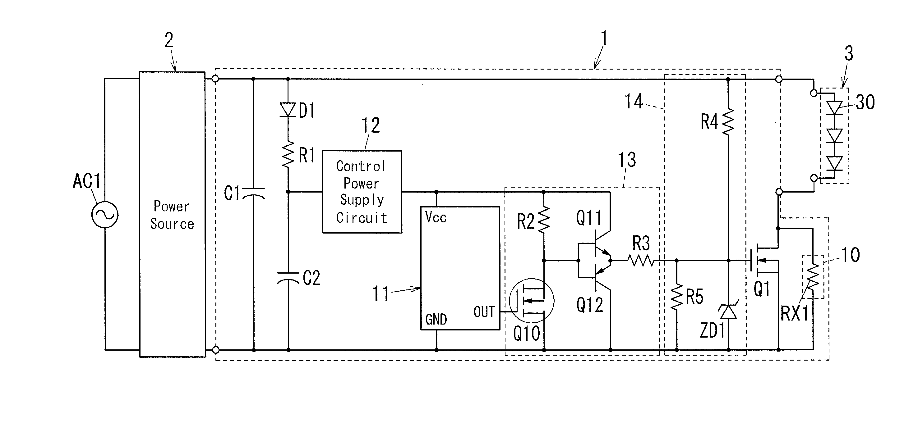
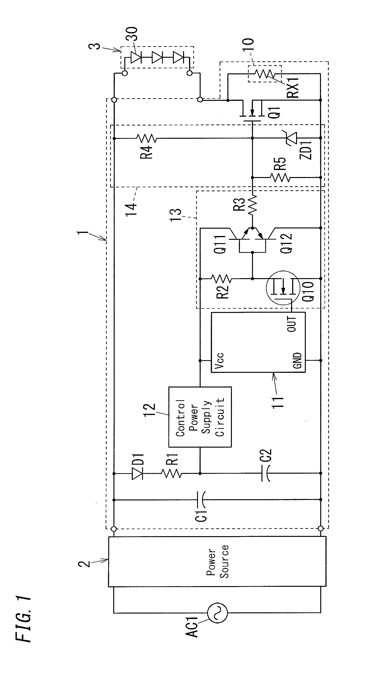
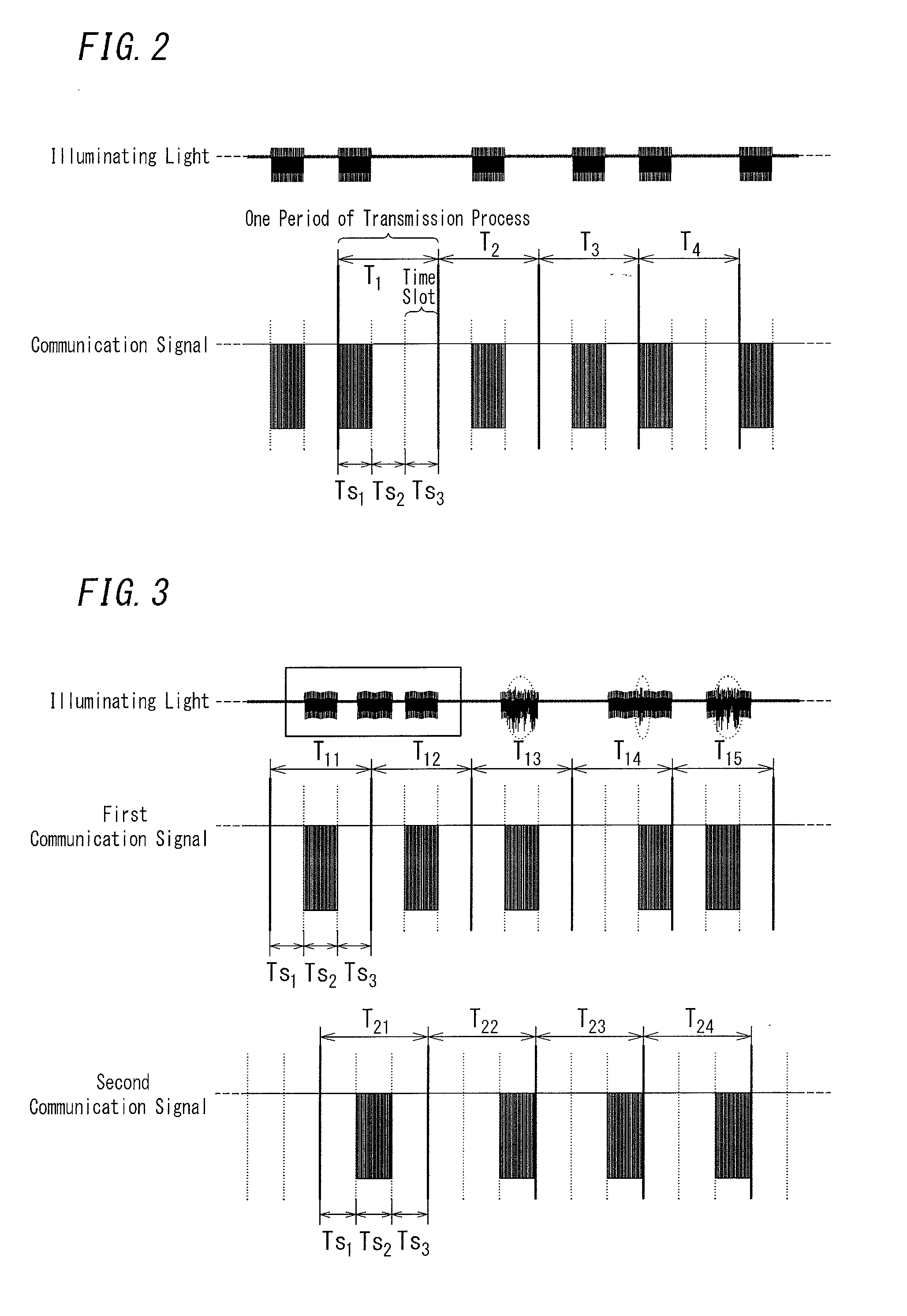
[0022]The visible light communication device 1 of one embodiment in accordance with the present invention includes a control circuit 11. The control circuit 11 is configured to superpose a communication signal on illuminating light by modulating an intensity of the illuminating light outputted from a light source 3 constituted by at least one light emitting diode 30 (light emitting device). The control circuit 11 repeats a transmission process of dividing a constant time period into a plurality of time slots and outputting the communication signal in a time slot arbitrarily selected from the plurality of time slots.

[0023]Hereinafter, the visible light communication device 1 of the present embodiment is described with reference to the drawings. The visible light communication device 1 of the present embodiment is to be connected between a power source 2 and the light source 3, as shown in FIG. 1

[0024]The visible light communication device 1 of the present embodiment includes an imped...


PUM


Abstract

The visible light communication device includes a control circuit configured to repeat a transmission process of transmitting a communication signal through modulating an intensity of visible light to be emitted from a light source. The control circuit is configured to, in the transmission process, arbitrarily select a time slot for transmission from a plurality of time slots set within a predetermined time period allocated to the transmission process, and transmit the communication signal in the time slot for transmission.

Description

CROSS-REFERENCE TO RELATED APPLICATIONS[0001]The application is based upon and claims the benefit of priority from Japanese Patent Application No. 2013-144977, filed on Jul. 10, 2013, the entire contents of which are incorporated herein by reference.TECHNICAL FIELD[0002]The disclosure relates to a visible light communication device for communication using visible light as a medium, a lighting fixture including the same, and a lighting system.BACKGROUND ART[0003]In the past, there has been proposed a lighting fixture that includes a light source constituted by at least one light emitting diode (LED) and sends a signal by modulating an intensity of illuminating light. Such a lighting fixture is disclosed in document 1 (JP 2012-069505 A), for example. This type of illuminating light communication device modulates the illuminating light itself, and thereby sends a signal. Hence, a special device such as an infrared communication device is unnecessary. Further, use of light emitting diod...

Claims


Application Information

Patent Timeline
IPC IPC(8): H04B10/116H04J3/16
CPCH04B10/116H04J3/1694
Inventor HARUYAMA, SHINICHIROSUZUKI, SHUJIKIDO, SHOJIROUSHIOHAMA, EIJI
Owner PANASONIC CORP
Features
  • Generate Ideas
  • Intellectual Property
  • Life Sciences
  • Materials
  • Tech Scout
  • Unparalleled Data Quality
  • Higher Quality Content
  • 60% Fewer Hallucinations
Learn More