
Wind turbine rotor

Inactive Publication Date: 2015-01-15
ALSTOM RENEWABLE TECH
View PDF7 Cites 7 Cited by
  • Summary
  • Abstract
  • Description
  • Claims
  • Application Information

AI Technical Summary

Benefits of technology

The patent text describes a pitch bearing system for wind turbines. The system includes a disc that is connected to the blade, which helps to reduce stress and fatigue on the bearing. The disc also increases the stiffness of the connection between the blade and the bearing, improving its reliability and durability. Additionally, the patent proposes the use of an annular gear that covers a 95° arc segment, which helps to minimize the amount of gear material used in wind turbines. The gear may be made from a plurality of arc segments, allowing for easy repair or replacement. The pitch system may also include a lubrication system, which can be arranged on the disc and provides protection from damage without the need for an additional cover.

Problems solved by technology

This way, some of the rolling elements of the bearing may carry larger loads than others, thus deforming the pitch bearing.
In those cases, the loads acting on the bearing may cause the linear contact and load transmission between the driven gear and the drive pinion to be shifted from its nominal position and the gear meshing (and the bearing) of such systems may thus suffer deformations.
Furthermore, the studs or bolts connecting the blades to the bearing may also be subjected to such uneven loads when gusts of wind impinge on a blade and they may develop cracks, which ultimately may cause them to fail.
However, this would add weight and cost to the design.
But this kind of solution can be rather cumbersome to mount and therefore expensive.

Method used


Image

  • Wind turbine rotor
  • Wind turbine rotor
  • Wind turbine rotor

Examples


first embodiment

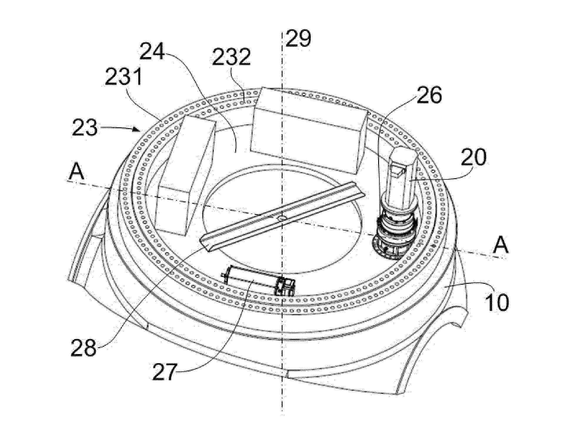
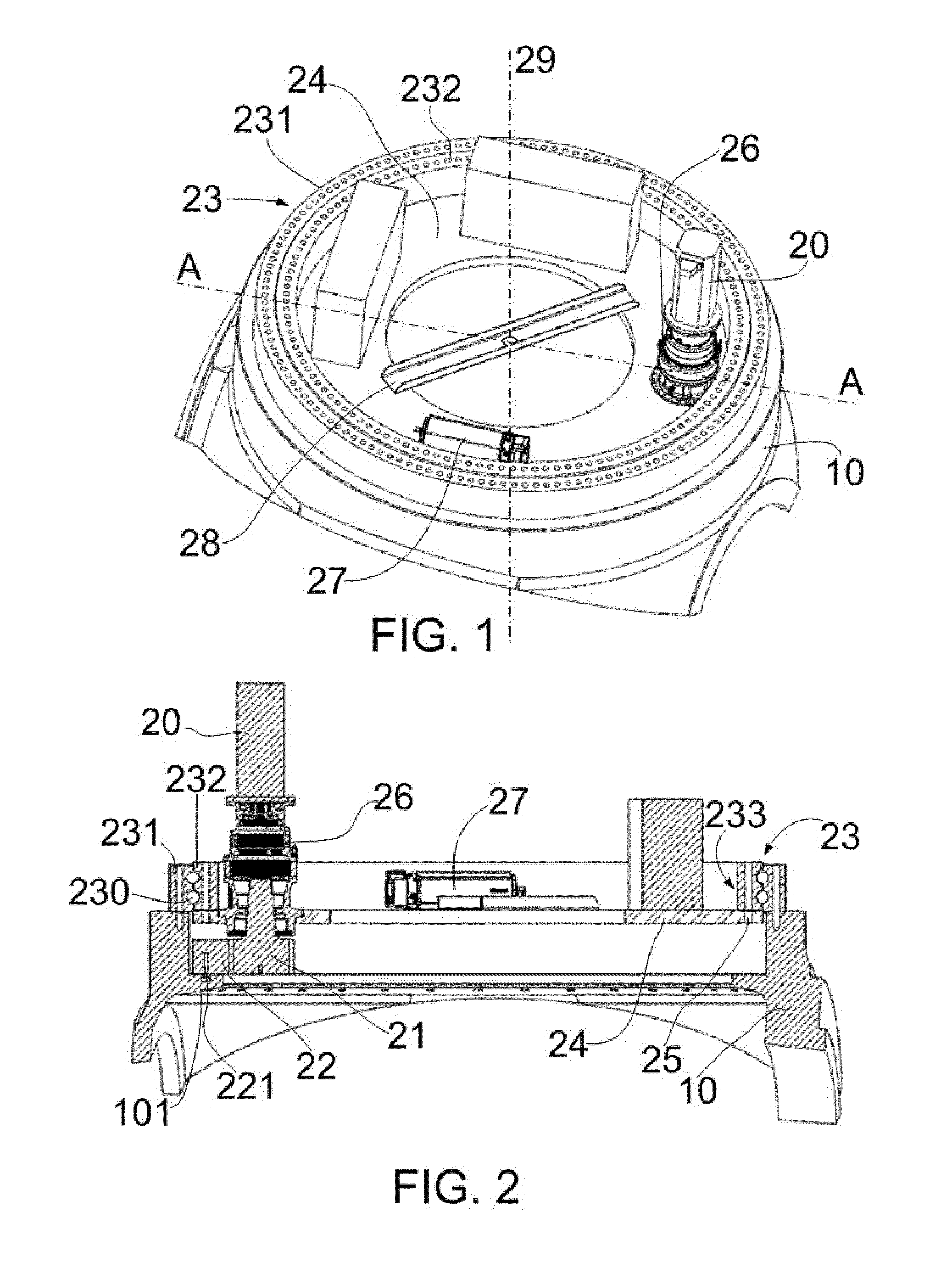
[0025]FIG. 1 shows a perspective view of a wind turbine rotor according to a

[0026]The rotor may comprise a hub 10 to which a plurality of blades (not shown) may be rotatably attached. Pitch systems may be provided for rotating each of the blades substantially along its longitudinal axis. A pitch system may comprise a motor 20, a drive pinion (see FIG. 2), an annular gear (see FIG. 2) arranged to mesh with the drive pinion and a pitch bearing 23. The bearing 23 may comprise an outer bearing ring 231 connected with the hub 10 and an inner bearing ring 232 connected with a blade (not shown). Further, a reinforcing disc 24 may be fixed to the inner bearing ring 232 at a side facing the hub 10. The same studs (see FIG. 2) that connect the blade to the bearing 23 may be used for fixing the reinforcing disc 24 and they may thus be relatively long. In the example of FIG. 1 the reinforcing disc may be an annular disc or a ring.

[0027]Furthermore, the pitch system may further comprise a reduce...

second embodiment

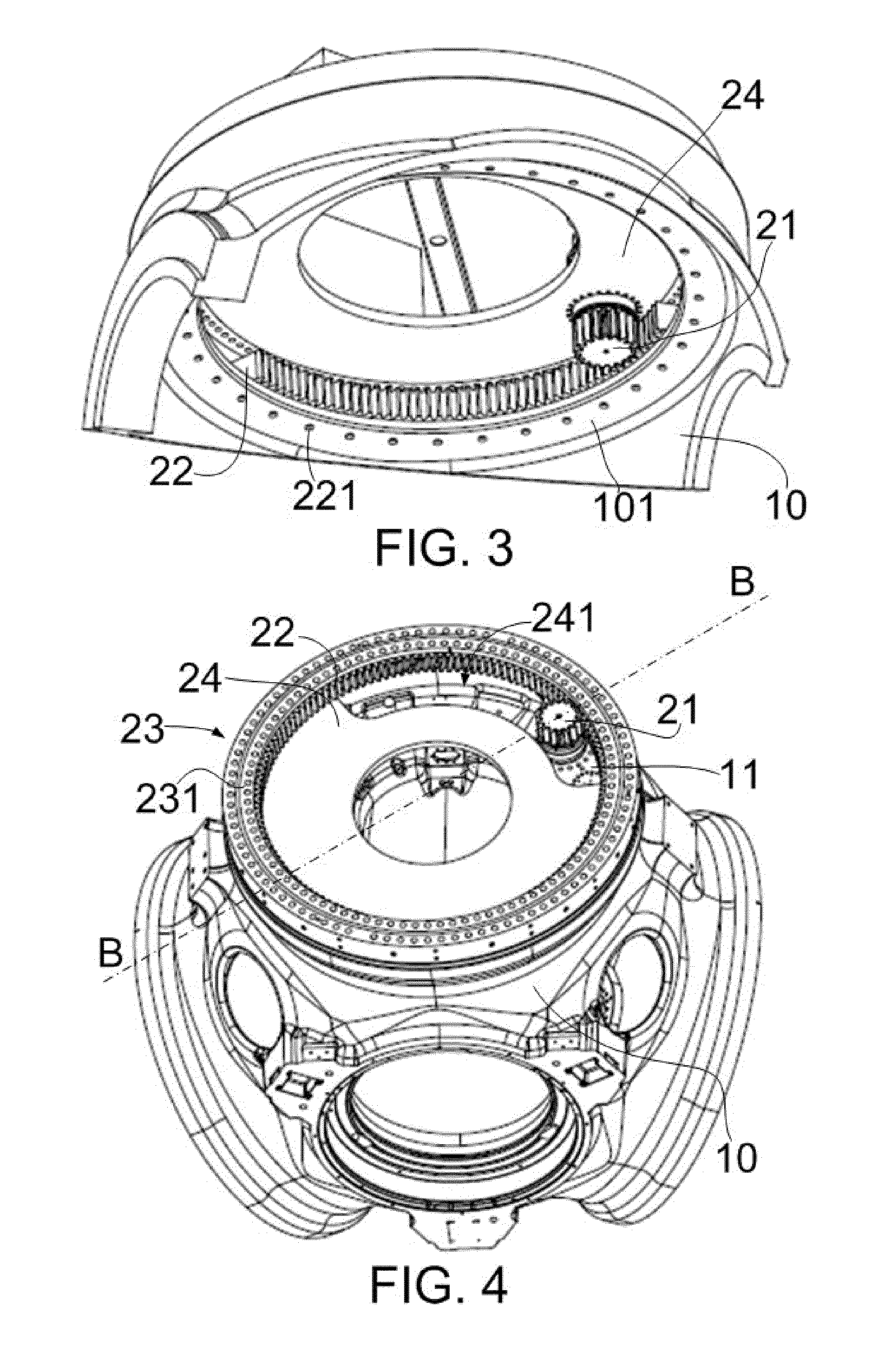
[0035]FIGS. 4 and 5 show a perspective view and a cross-sectional view respectively of a wind turbine rotor in which the inner bearing ring 231 may comprise an annular gear 22 which may mesh with a drive pinion 21 of a drive motor (not shown) fixed to the hub 10. In this case, the reinforcing ring 24 may comprise a curved elongated hole 241 through which the drive pinion 21 can mesh with the annular gear 22.

[0036]According to FIGS. 4 and 5, the hub 10 may comprise a flange 11 for mounting the drive pinion 21. In some embodiments, the flange may form an integral piece with the hub. In others it may be a separate piece fixed to the hub by welding or by fastening means such as screws, bolts or similar.

[0037]The length in an axial direction (thickness) of a reinforcing disc may substantially depend on the size of the wind turbine blade and the forces acting on it and may be approximately between 30-150 mm, e.g. between 50-120 mm.

[0038]In further embodiments the reinforcing ring may be ...


PUM


Abstract

Wind turbine rotor comprising a hub (10), blades and at least one pitch system for rotating a blade along its longitudinal axis, the pitch system comprising a motor, a drive pinion, an annular gear arranged to mesh with the drive pinion and a pitch bearing that comprises an outer bearing ring, an inner bearing ring and, between these two bearing rings, one or more rows of rolling elements allowing both bearing rings to rotate relative to each other. One of the hub and blade is connected to the inner bearing ring and the other of the hub and blade is connected to the outer bearing ring, and wherein a reinforcing disc (24) is axially fixed to the bearing ring to which the blade is connected at a side facing the hub, the disc being fixed to the bearing ring by the same fasteners connecting the blade to the bearing.

Description

[0001]This application claims the benefit of European Patent Application 12382042.5 filed on Feb. 6, 2012 and U.S. Provisional Patent Application Ser. No. 61 / 621,204 filed on Apr. 6, 2012.[0002]The present invention relates to wind turbine rotors, and more particularly relates to wind turbine rotors comprising at least one electromechanical pitch mechanism. The invention further relates to a wind turbine comprising the same.BACKGROUND ART[0003]Modern wind turbines are commonly used to supply electricity into the electrical grid. Wind turbines generally comprise a rotor with a rotor hub and a plurality of blades. The rotor is set into rotation under the influence of the wind on the blades. The rotation of the rotor shaft drives the generator rotor either directly (“directly driven”) or through the use of a gearbox.[0004]An important auxiliary system generally provided on wind turbines is the pitch system. Pitch systems are employed for adapting the position of a wind turbine blade to...

Claims


Application Information

Patent Timeline
IPC IPC(8): F03D7/02F03D7/04
CPCF03D7/0224F03D7/04F03D1/065F05B2240/54F05B2260/4031F05B2260/79F16C19/08F16C33/586F16C2360/31F03D13/10F03D80/50F03D80/70Y02E10/72
Inventor PASQUET, PIERRECANEDO PARDO, SANTIAGO
Owner ALSTOM RENEWABLE TECH
Learn More