System for determining biofuel concentration

a biofuel concentration and biofuel technology, applied in the field of biofuel concentration determination, can solve the problems of inability to accurately detect the presence or concentration of biofuel in the fuel, the conversion process is expensive and labor-intensive, and the incompatibility of conventional engine systems with biofuel blends, etc., to achieve low cost and simple results

Active Publication Date: 2015-01-15
UT BATTELLE LLC
View PDF2 Cites 0 Cited by
  • Summary
  • Abstract
  • Description
  • Claims
  • Application Information

AI Technical Summary

Benefits of technology

The patent describes a responsive material that can change its shape or size when exposed to different components of a fuel blend. This material is specifically designed to be soluble to biofuel but insoluble to other components, such as contaminants and additives. By measuring the changes in the material's shape or size, the device can accurately detect the presence or concentration of biofuel in the fuel. This technology provides a low-cost and simple way to detect biofuel in fuel blends.

Problems solved by technology

Although biofuels have made their way into the market, some conventional engine systems are incompatible with fuel blends including biofuels.
An incompatible system may be reconfigured for compatibility, but often times, this conversion process is expensive and labor intensive.
An ethanol free source may be difficult to locate, and there may be no guarantee that fuel advertised as 100% gasoline does in fact contain no ethanol by its outward appearance.
But, these conventional flex fuel sensors are considered by many to be expensive, unreliable, and inefficient energy consumers.
They may also be highly sensitive to contaminants, particularly to water, prevalent in many fuel blends.
Both types, however, have two primary downsides: they are in many cases expensive to manufacture and maintain, and they may be highly sensitive to fuel contaminants, particularly water.
Thus, accurate measurements may not be obtainable using a dielectric sensor unless fuel contamination is low or below a threshold.
The refractive index (or optical) sensor may also be impacted by contaminants, such as water.
This sensor technique may be less sensitive to contaminants than the dielectric method, but it is considered by many to be more complex in structure, and therefore more expensive.
These windows may become dirty such that maintenance and replacement are frequent considerations.

Method used


Image

  • System for determining biofuel concentration
  • System for determining biofuel concentration

Examples


first embodiment

A. First Embodiment

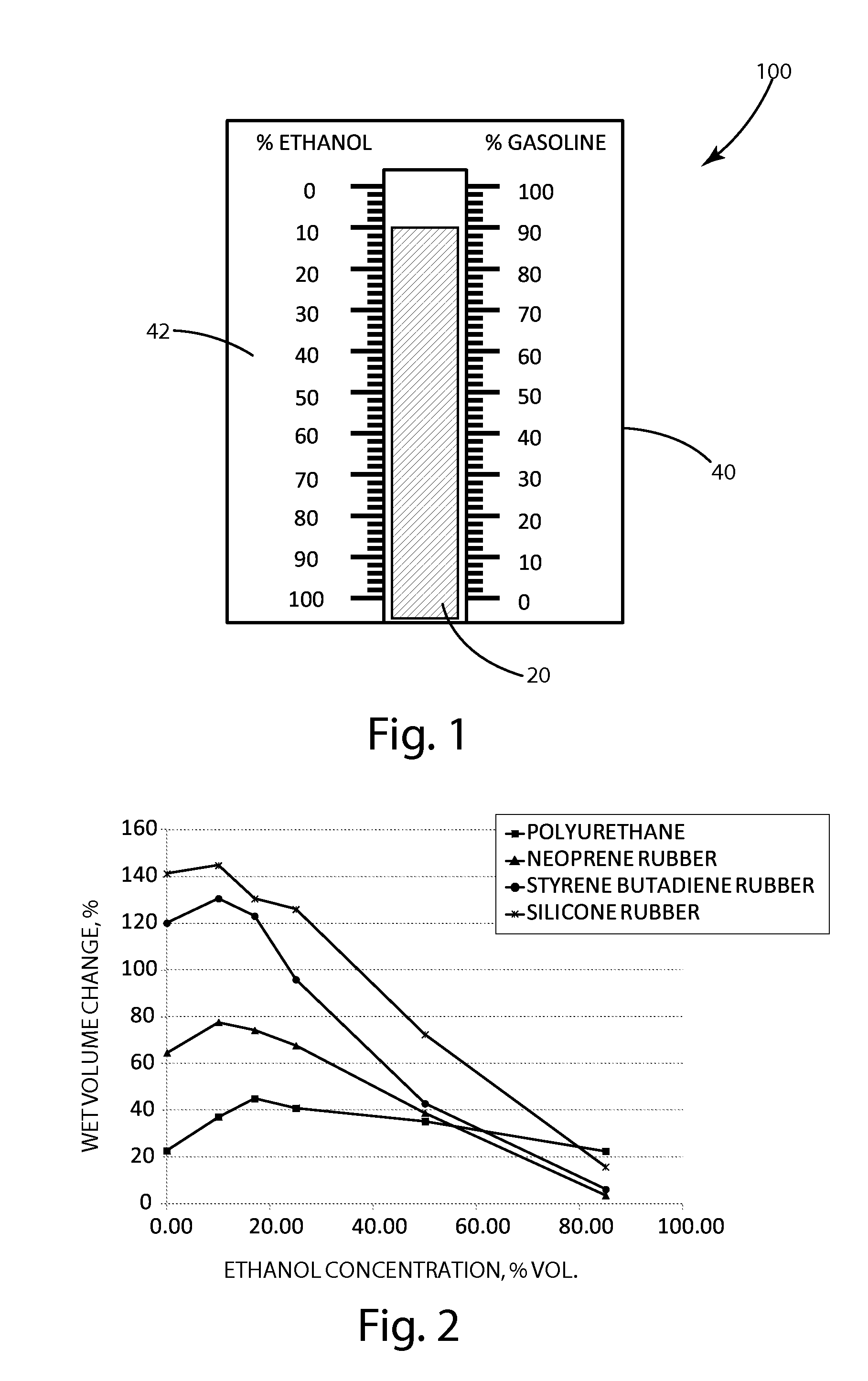
[0020]A measurement device in accordance with one embodiment is shown in FIG. 1 and designated 100. The measurement device 100 may include a responsive material 20 configured to aid in measuring a biofuel concentration of a fuel blend. The responsive material 20 may change dimensionally in proportion to changes in biofuel concentration. For example, the responsive material 20 may increase in volume or swell as the percentage of biofuel within a fuel blend decreases. By knowing the relationship between the concentration of biofuel within a fuel blend and a dimensional property of the responsive material 20, the concentration of biofuel may be determined by directly or indirectly measuring a dimensional property of the responsive material 20.

[0021]For example, the plot in FIG. 2 shows an experimentally determined relationship between ethanol content in gasoline and volume for a variety of responsive materials, including polyurethane, neoprene rubber, styrene butadie...

second embodiment

B. Second Embodiment

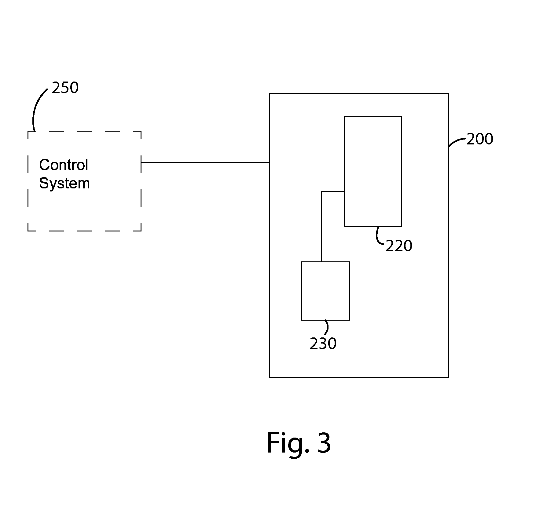
[0027]Turning now to FIG. 3, a measurement device in accordance with another embodiment is shown, and designated 200. The measuring device 200 may be similar to the measuring device 100 but with several exceptions. The measuring device 200 may include a responsive material 220 similar to the responsive material 20 described with respect to the illustrated embodiment of FIG. 1. For example, the responsive material 220 may be formed of silicone rubber configured to change in proportion to changes in biofuel concentration, such as by changing dimensionally in response to changes in biofuel concentration.

[0028]The measuring device 200 may also include a sensor 230 configured to provide an output based on one or more properties of the responsive material 220, which may be sensed directly or indirectly. Because these properties may be proportional to the biofuel concentration, measurements conducted by the sensor 230 may be used as a basis for providing an output corre...


PUM

PropertyMeasurementUnit
concentrationaaaaaaaaaa
thicknessaaaaaaaaaa
volumeaaaaaaaaaa

Abstract

A measurement device or system configured to measure the content of biofuels within a fuel blend. By measuring a state of a responsive material within a fuel blend, a biofuel content of the fuel blend may be measured. For example, the solubility of a responsive material to biofuel content within a fuel blend, may affect a property of the responsive material, such as shape, dimensional size, or electrical impedance, which may be measured and used as a basis for determining biofuel content.

Description

[0001]This invention was made with government support under Contract No. DE-AC05-000R22725 awarded by the U.S. Department of Energy. The government has certain rights in the invention.BACKGROUND OF THE INVENTION[0002]The present invention relates to determining biofuel concentration, and more specifically to determining biofuel concentration in petroleum-derived fuels.[0003]Biofuels are being added more frequently to petroleum-derived fuels (also known as petrofuels), often times to supplement the more scarce or costly petrofuels. This type of fuel mixture is called a fuel blend, and may include a variety of fuels, such as biofuel, petrofuel, or any other fuel, or a combination thereof. One such fuel blend includes a low level of ethanol, a type of biofuel, and is referred to as E10. Another example of a fuel blend containing ethanol is called E15 and another example is called E85. And, yet another example of a fuel blend includes biodiesel, another type of biofuel.[0004]Although bi...

Claims


Application Information

Patent Timeline
Patent Type & Authority Applications(United States)
IPC IPC(8): G01N33/28
CPCG01N33/2852
Inventor HUFF, SHEAN P.JANKE, CHRISTOPHER JAMESKASS, MICHAEL D.LEWIS, SR., SAMUEL ARTHURPAWEL, STEVEN J.THEISS, TIMOTHY J.
Owner UT BATTELLE LLC
Why Eureka
Try Eureka