
Rrh concealment module/methods in natural convection

Active Publication Date: 2015-01-15
COMMSCOPE TECH LLC
View PDF5 Cites 22 Cited by
  • Summary
  • Abstract
  • Description
  • Claims
  • Application Information

AI Technical Summary

Benefits of technology

The invention is a concealed remote radio head assembly that has a cylindrical concealment module with perforated panels. The perforated panels are evenly spaced around the module's circumference. The assembly also includes three remote radio heads that are mounted on a support, with each radio head associated with one of the perforated panels. A baffle is also included to prevent cool air from being diverted between the radio heads and the support. The technical effect of this invention is a more efficient and effective concealing mechanism for remote radio heads.

Problems solved by technology

This concealment becomes a challenge for any active components that are generating heat.
Current Concealment methods do not provide adequate cooling.
In instances where there are openings in the concealment radomes, they are typically too small and located below the RRHs with no exhaust vents to allow the heated air to be released.
This lack of proper ventilation and airflow will result in the overheating of the RRHs, and a shortened product life.
Currently known strategies to cope with inadequate cooling have performance and cost disadvantages.
With current concealed solutions not providing adequate cooling, the RRHs are often placed at ground level or outside of the concealment module.
Such ground installations result in higher power consumption and energy costs, as well as decreased performance due to the transmission losses from long RF jumper cables connecting the RRHs to the antennas at the top of the tower.
When RRHs are placed outside of the concealment module but still on the tower structure, the RRHs lose the aesthetic advantages of concealment and often violate zoning requirements.
There are also issues with accessibility.
Accessing the equipment within the concealment becomes difficult as the entire cylinder must be removed.

Method used


Image

  • Rrh concealment module/methods in natural convection
  • Rrh concealment module/methods in natural convection
  • Rrh concealment module/methods in natural convection

Examples


Embodiment Construction

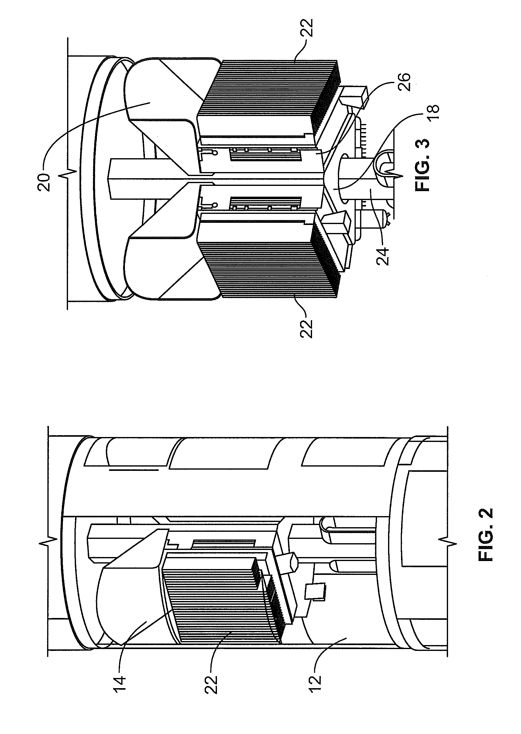
[0012]One way to overcome the limitations of concealing RRHs or any active heat generating components is to ensure proper ventilation, air-flow direction, and equipment orientation. One aspect of this invention relates to concealing groups of RRHs or radio modules inside a single concealed compartment. Multiple groups of RRH can be concealed using proper spacing and orientation.

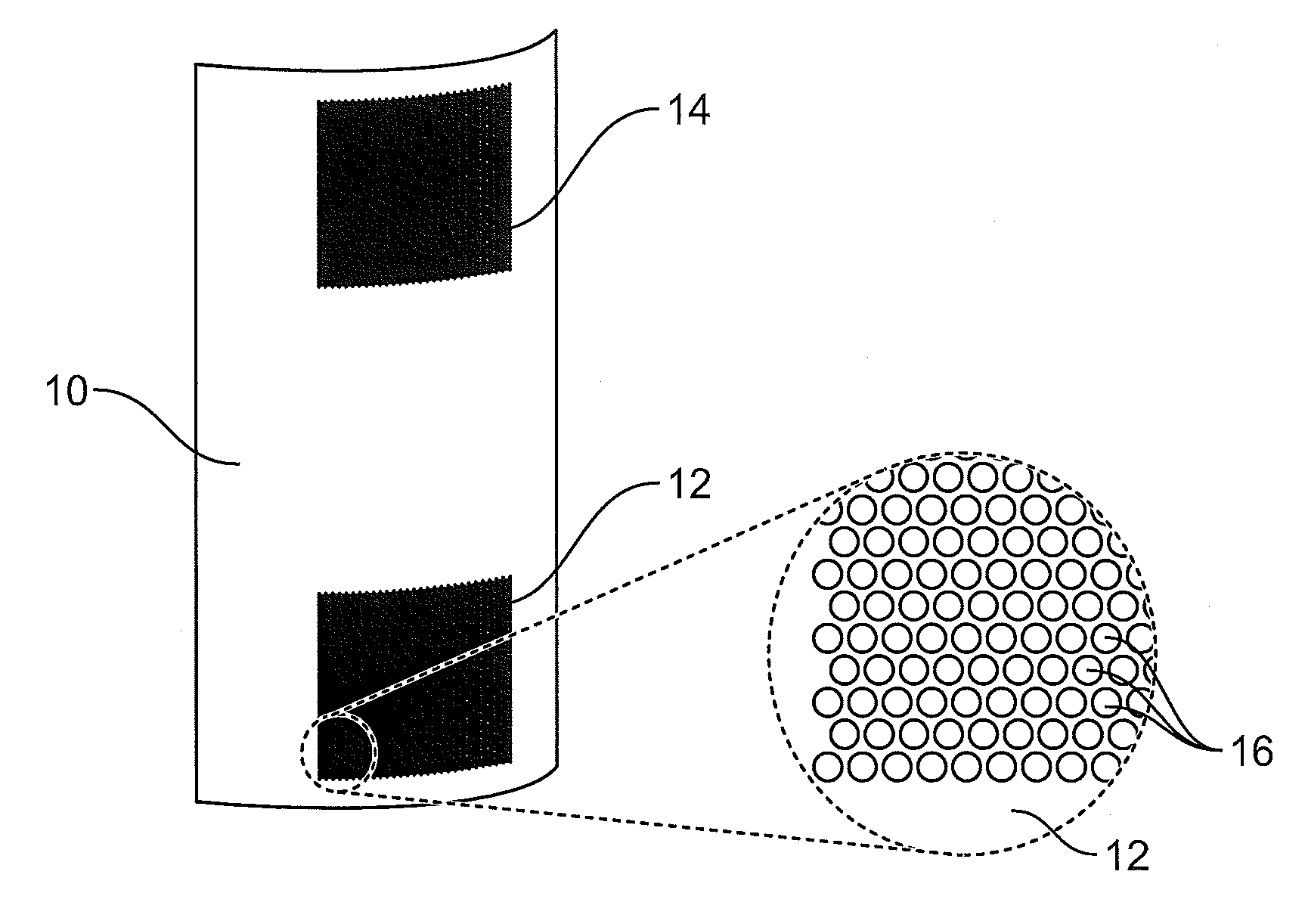
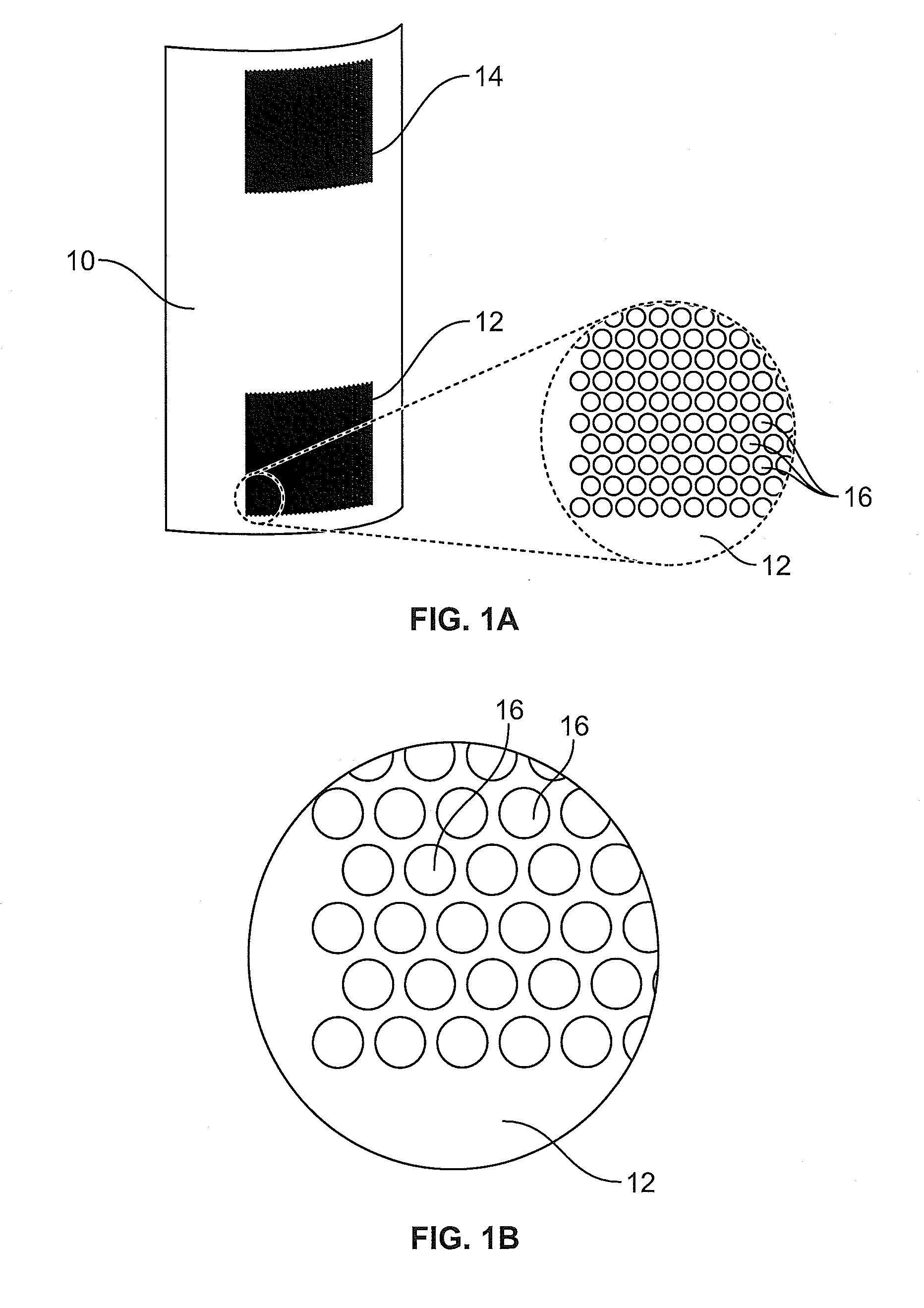
[0013]As shown in FIG. 2, the concealment panels 10 have optimized ventilation areas to allow proper inlet 12 and outlet 14 air flow and cooling. The ventilation panels have associated baffle components 18 to ensure that all air is flowing over the heat generating equipment. The equipment is also orientated so that the exhaust air that has been heated does not flow into the ventilation panels of adjacent equipment.

[0014]The RRH modules are enclosed behind optimized ventilation panels 10. The panels contain strategically sized openings 16 to provide maximum open area, best manufacturability, insect resistance,...


PUM


Abstract

Disclosed is an apparatus with a concealment module, the concealment module including an inlet panel and an outlet panel, the outlet panel located higher than the inlet panel. Also included is a remote radio head disposed with the concealment module, mounted on a support, and located between the inlet panel and the outlet panel. A first baffle is located under the remote radio head to prevent cool air from the inlet panel from being diverted to a space between the remote radio head and the support. A second baffle is located to direct cooling air over a back of the remote radio head. A third baffle is located on top of the remote radio head to direct heated cooling air to the outlet panel. A fourth baffle is located to direct cooling air over the front of the remote radio head.

Description

BACKGROUND OF THE INVENTION[0001]A wireless radio network system consists of a base band unit (BBU), a remote radio head (RRH or sometimes referred to as RRU) and an antenna. As more wireless capacity is required, additional wireless sites are necessary to handle the ever-growing need for additional bandwidth and coverage. As these wireless sites move closer to urban areas and within municipalities, hiding or concealing this network equipment is often preferred. In many cases local zoning regulations require the concealment of said equipment. This concealment becomes a challenge for any active components that are generating heat. This is especially true for the remote radio head (RRH) modules, the device that broadcasts the radio frequency signal in a wireless system. These devices require adequate cooling and ventilation to operate properly. In this invention the BBU is located outside of the concealment and not at the top of the tower.[0002]Current Concealment methods do not provi...

Claims


Application Information

Patent Timeline
IPC IPC(8): H04B1/036
CPCH04B1/036H01Q1/02H01Q1/246H05K7/20127
Inventor COLAPIETRO, JULIAN R.HENDRIX, WALTER MARKSIVANANDAN, DEEPAK KUMAR
Owner COMMSCOPE TECH LLC
Learn More