Stereoscopic endscope system
a technology of endoscope and stereoscopic lens, which is applied in the field of stereoscopic endoscope system, can solve problems such as difficult grasping of information
- Summary
- Abstract
- Description
- Claims
- Application Information
AI Technical Summary
Benefits of technology
Problems solved by technology
Method used
Image

Examples
first embodiment
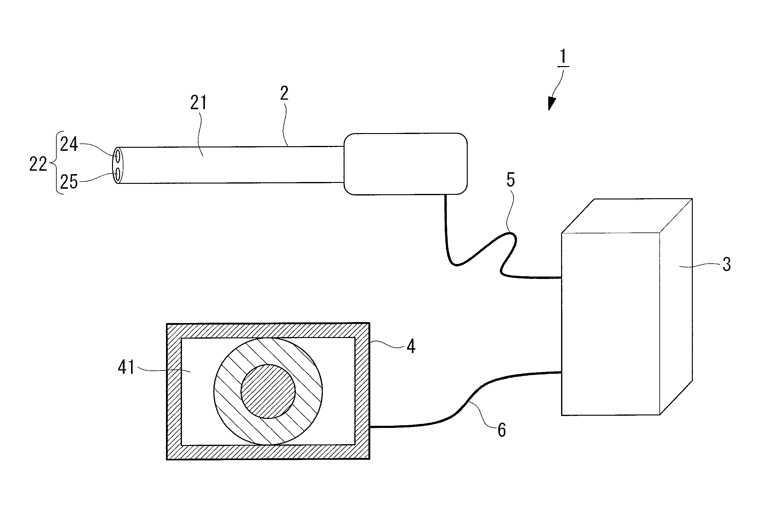
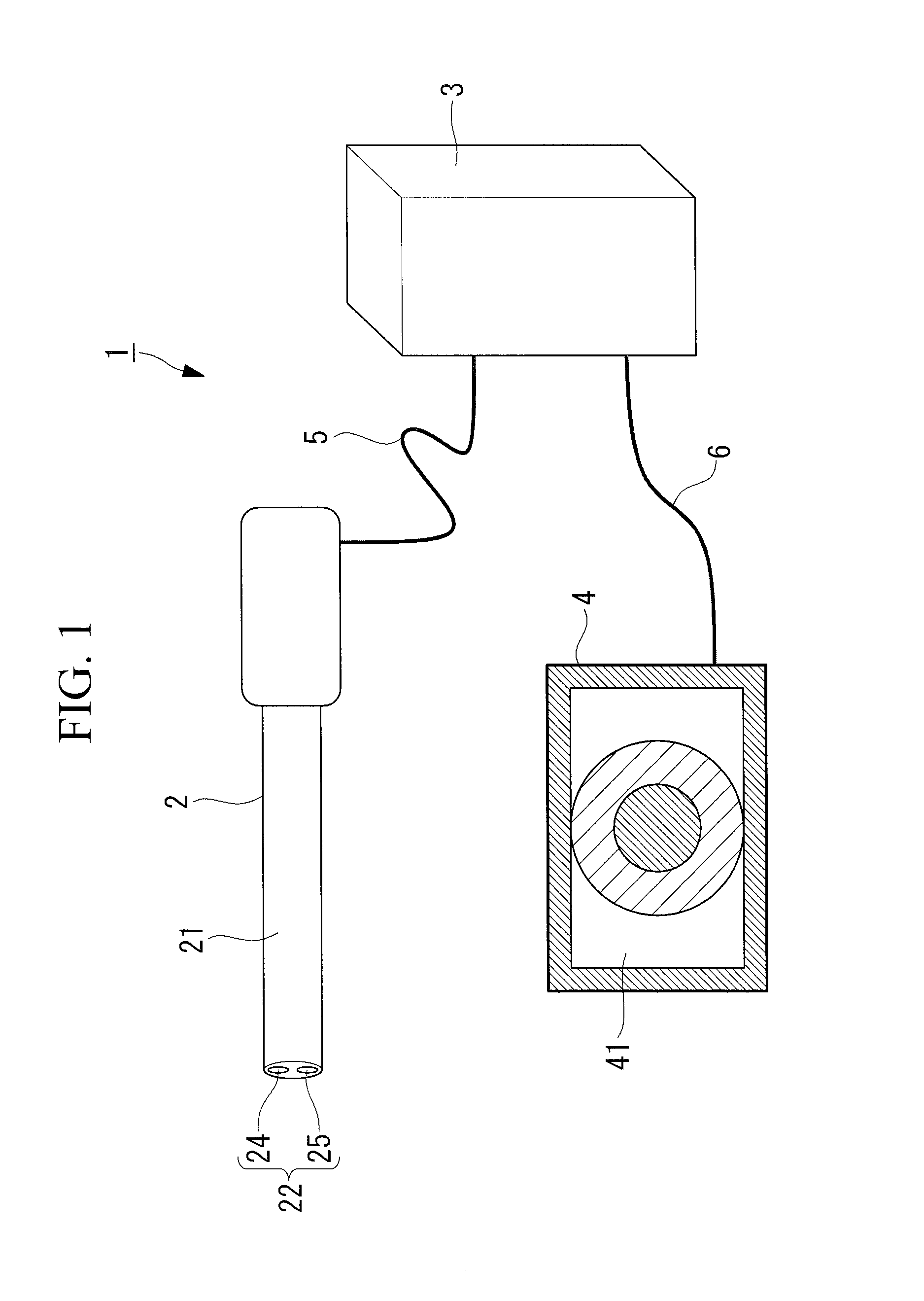
[0034]First, an overall configuration of the stereoscopic endoscope system 1, which is common among the plurality of embodiments of the present invention, will be described with reference to FIG. 1.
[0035]As illustrated in FIG. 1, the stereoscopic endoscope system 1 includes an endoscope 2 that is inserted into a body cavity (subject) of a person to be operated and captures an image of the inside of the body cavity, an image processing apparatus 3 that processes the image captured by the endoscope 2, and an image display apparatus 4 that displays the image processed by the image processing apparatus 3.
[0036]The endoscope 2 includes an image capturing unit 22 for capturing an image at a leading edge of a cylindrical casing (insertion unit) 21 while having a circuit unit (not illustrated), which converts the image captured by the image capturing unit 22 into an electric signal, accommodated in the casing 21. The electric signal obtained by the conversion in the circuit unit is output t...
second embodiment
[0051]As illustrated in FIG. 4, in the present embodiment, photographing lenses 24 and 25 constituting an image capturing unit 22 in an endoscope 2 are set so that either one of their angles of view θ4 and θ5 or their diameters becomes larger depending on the dominant eye of an observer.
[0052]If the dominant eye of the observer is a right eye, as illustrated in FIG. 4 (a), for example, the angle of view θ5 of one, which is positioned on the right side of an image capturing target, of the photographing lenses 24 and 25, for example, the photographing lens (first image capturing unit) 25 is set to be larger than the angle of view θ4 of the other photographing lens (second image capturing unit) 24 (e.g., the angle of view θ4=60° and the angle of view θ5=120°). If the dominant eye of the observer is a left eye, as illustrated in FIG. 4 (b), the angle of view θ4 of the photographing lens (first image capturing unit) 24, for example, is set to be larger than the angle of view θ5 of the ot...
third embodiment
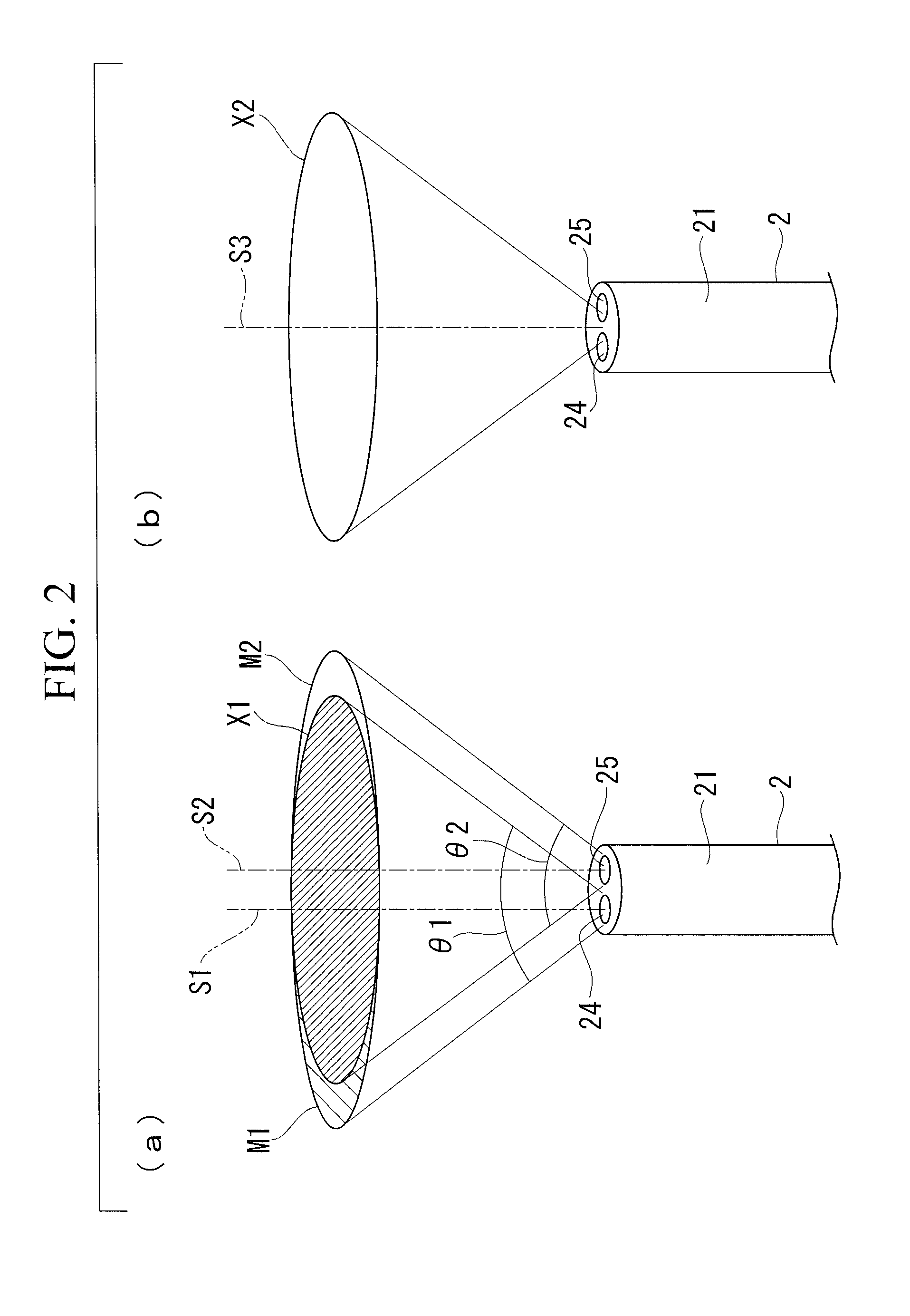
[0062]As illustrated in FIG. 6, in the present embodiment, photographing lenses 24 and 25 constituting an image capturing unit 22 in an endoscope 2 are arranged so that their respective optical axes S1 and S2 are parallel to each other and spaced a predetermined distance apart from each other in a direction perpendicular to an axis of a casing 21 in the endoscope 2. The photographing lenses 24 and 25 are set so that their respective numbers of pixels are the same and either one of their respective angles of view θ7 and θ8 becomes larger. In the present embodiment, the angle of view θ8 of the photographing lens (first image capturing unit) 25 is set larger than the angle of view θ7 of the photographing lens (second image capturing unit) 24.
[0063]As illustrated in FIGS. 5 and 6, in an image processing apparatus 3, data representing a stereoscopic image (three-dimensional image) X7 having a parallax is generated from an image (second image) M7 acquired via the photographing lens 24 and...
PUM
 Abstract
Description
Claims
Application Information
 - R&D
- Intellectual Property
- Life Sciences
- Materials
- Tech Scout
- Unparalleled Data Quality
- Higher Quality Content
- 60% Fewer Hallucinations
Browse by: Latest US Patents, China's latest patents, Technical Efficacy Thesaurus, Application Domain, Technology Topic, Popular Technical Reports.
© 2025 PatSnap. All rights reserved.Legal|Privacy policy|Modern Slavery Act Transparency Statement|Sitemap|About US| Contact US: help@patsnap.com