Resuscitation assembly with peep valve

a technology of resuscitation assembly and peep valve, which is applied in the field of resuscitation assembly with peep valve, can solve the problems of ineffective ventilation, high cost, and difficult to spot, and achieve the effect of easy replacement and low cos

Inactive Publication Date: 2015-01-15
LAERDAL GLOBAL HEALTH
View PDF16 Cites 12 Cited by
  • Summary
  • Abstract
  • Description
  • Claims
  • Application Information

AI Technical Summary

Benefits of technology

[0018]Such a cap can exhibit a circular body with a circular protrusion or a circular groove arranged in the inwardly facing face of said circular body. With such an embodiment the cap (i.e. the expiration indicator) can easily be attached to a facing groove or protrusion, respectively, of the resuscitation assembly, for instance on the pipe stub.
[0019]Thus, an expiration indicator is provided which is cheap to manufacture and which easily can be replaced. It shall also be noted that the resuscitation assembly will function also when the expiration indicator is not present, of course then however without the functions of the expiration indicator / PEEP valve.

Problems solved by technology

This makes it expensive and cumbersome to clean.
One of the greatest challenges with lung ventilations today is to get a good seal between the patient mask and the face of the patient.
Ineffective ventilations can be hard to spot and can be critical for the patient.

Method used


Image

  • Resuscitation assembly with peep valve
  • Resuscitation assembly with peep valve
  • Resuscitation assembly with peep valve

Examples


Embodiment Construction

[0027]While the invention has be described in general terms above, a more detailed example of embodiment will now be described with reference to the drawings, in which

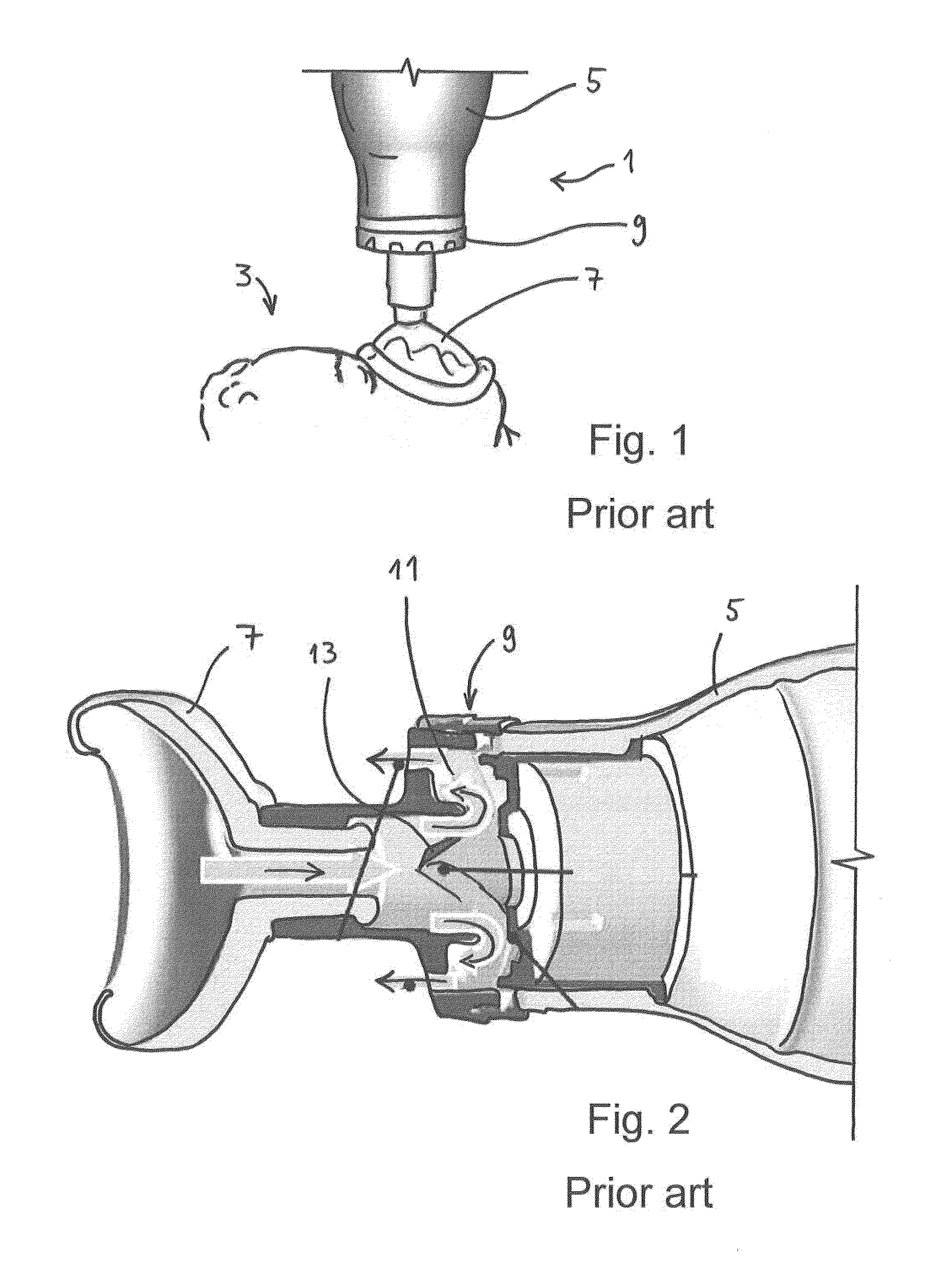
[0028]FIG. 1 is a side view of a ventilation assembly of the prior art in use on a patient;

[0029]FIG. 2 is a cross section view showing the valve assembly of a common ventilation assembly of the prior art;

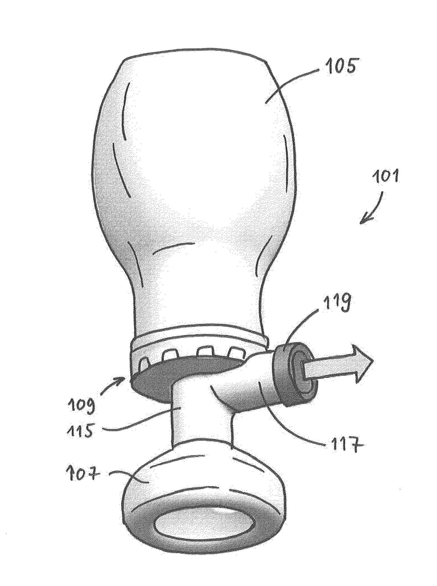
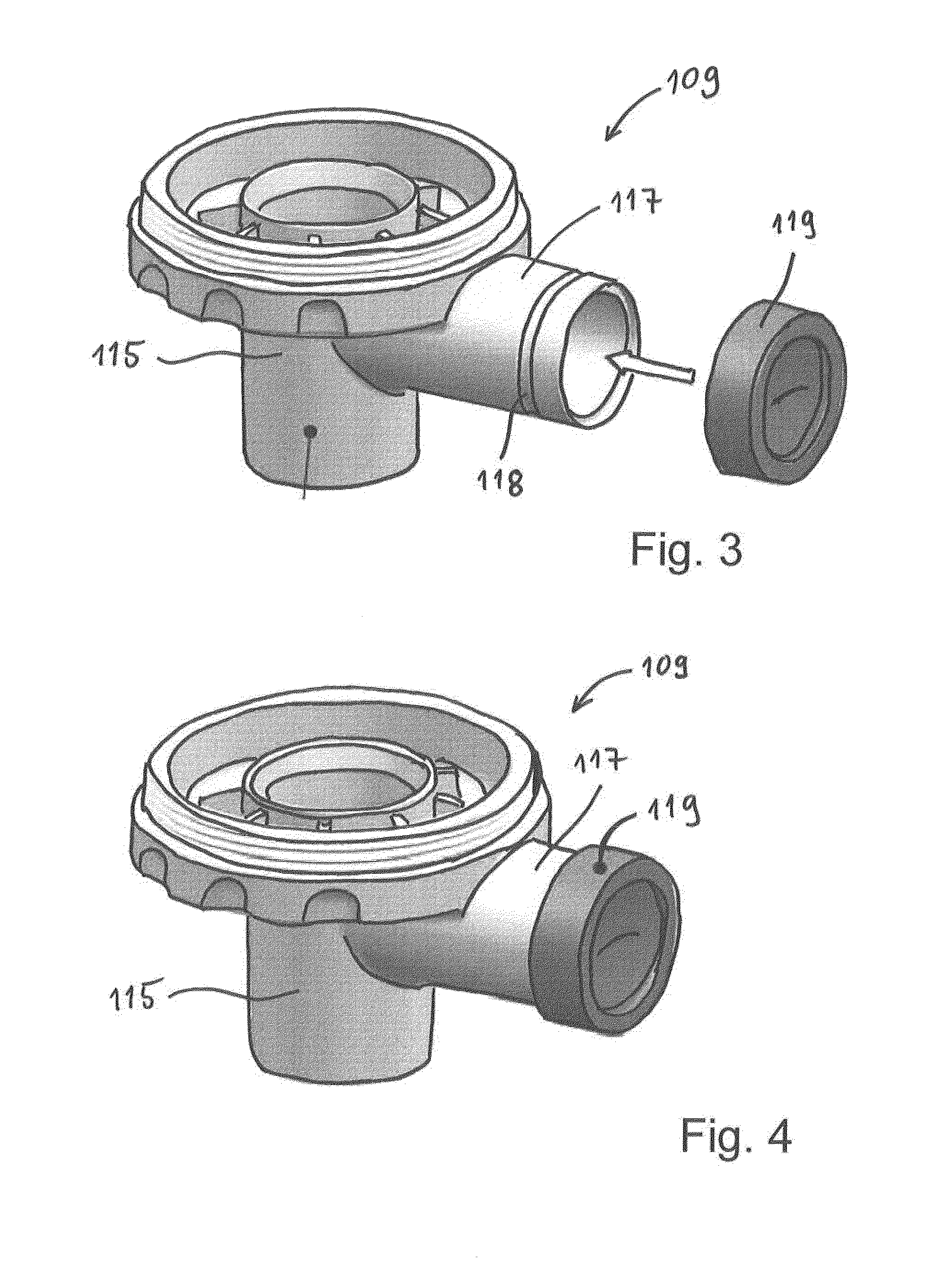
[0030]FIG. 3 is a perspective view of a valve assembly and an expiration indicator, being part of a resuscitation assembly according to the present invention;

[0031]FIG. 4 is a perspective view corresponding to FIG. 3, however with the expiration indicator attached to the valve assembly;

[0032]FIG. 5 is an enlarged perspective view of the expiration indicator shown in FIG. 3 and FIG. 4;

[0033]FIG. 6 is another enlarged perspective view of the expiration indicator;

[0034]FIG. 7 is a cross section view of the expiration indicator in a closed mode;

[0035]FIG. 8 is a cross section view of the expiration indicator in an open mo...


PUM


Abstract

Resuscitation assembly (101) comprising a patient mask (107), a ventilation bag (105), an inflation valve (113), an exhalation valve (111), and an expiration indicator (119). The expiration indicator (119) is a positive end expiratory pressure valve in the form of a slit valve that exhibits a slit (131) in a flexible sheet part (125). Also disclosed is a resuscitation assembly (101) comprising a patient mask (107), a ventilation bag (105), an inflation valve (113), an exhalation valve (111), a positive end expiratory pressure valve (119), and a pressure sensor (133) adapted to measure pressure on the patient side (127) of the positive end expiratory pressure valve (119).

Description

[0001]The present invention relates to a resuscitation assembly for artificial ventilation of the lungs of patients. In particular it regards to such an assembly which exhibits a positive end expiratory pressure valve.BACKGROUND[0002]When newborn babies do not begin to breathe spontaneously right after birth, they need artificial ventilation of the lungs to survive. This also applies to older children and adults in a non-breathing, unconscious state.[0003]Today, manual ventilations are usually given with a resuscitator. This is a device where a soft volume (usually referred to as a “silicone bag”) is squeezed by hand forcing fresh air into the mouth and lungs of the patient. Valve mechanisms guide inspiration air into the patient, while expiration air is lead out through a different exit-gate to make sure that no used air enters the silicone bag. New, fresh air is instead sucked into the silicone bag through another valve, making the resuscitator ready for the next inspiration of ai...

Claims


Application Information

Patent Timeline
Patent Type & Authority Applications(United States)
IPC IPC(8): A61M16/20A61M16/06A61B5/00A61B5/0205A61B5/113A61M16/00A61M16/08
CPCA61B5/742A61M16/0858A61B5/0205A61B5/024A61M16/0003A61M16/0084A61M16/06A61B5/113A61M16/208A61B5/08A61M2016/0027A61M16/0816A61M2205/3569A61M2205/3592A61M2205/8206
Inventor GOMO, OYSTEIN
Owner LAERDAL GLOBAL HEALTH
Why Eureka
Try Eureka