Helical coil mitral valve annuloplasty systems and methods

a technology of annuloplasty and helical coil, which is applied in the field of heart valve treatment, can solve the problems of distorting the shape of the mitral valve, and reducing the ejection volume of the left ventricl

Active Publication Date: 2015-01-15
MEDTRONIC INC
View PDF3 Cites 152 Cited by
  • Summary
  • Abstract
  • Description
  • Claims
  • Application Information

AI Technical Summary

Problems solved by technology

This results in reduced ejection volume from the left ventricle, causing the left ventricle to compensate with a larger stroke volume.
The increased workload eventually results in dilation and hypertrophy of the left ventricle, further enlarging and distorting the shape of the mitral valve.
If left untreated, the condition may result in cardiac insufficiency, ventricular failure, and ultimately death.
Rigid annuloplasty rings have the disadvantage of causing the mitral valve annulus to be rigid and unable to flex in response to the contractions of the ventricle, thus inhibiting the normal, three-dimensional movement of the mitral valve that is required for it to function optimally.
This eventually leads to scar tissue formation and loss of flexibility and function of the mitral valve.
Similarly, combination rings must generally be sutured in place and also cause scar tissue formation and loss of mitral valve flexibility and function.
One drawback to open-heart surgical techniques is that heart bypass procedures are required to accomplish replacement and / or repair of the valve.
Another drawback is that the open-heart procedures require that the patient undergo general anesthesia for a prolonged period of time.
However, the described minimally invasive delivery techniques may be less than optimal.

Method used


Image

  • Helical coil mitral valve annuloplasty systems and methods
  • Helical coil mitral valve annuloplasty systems and methods
  • Helical coil mitral valve annuloplasty systems and methods

Examples


Embodiment Construction

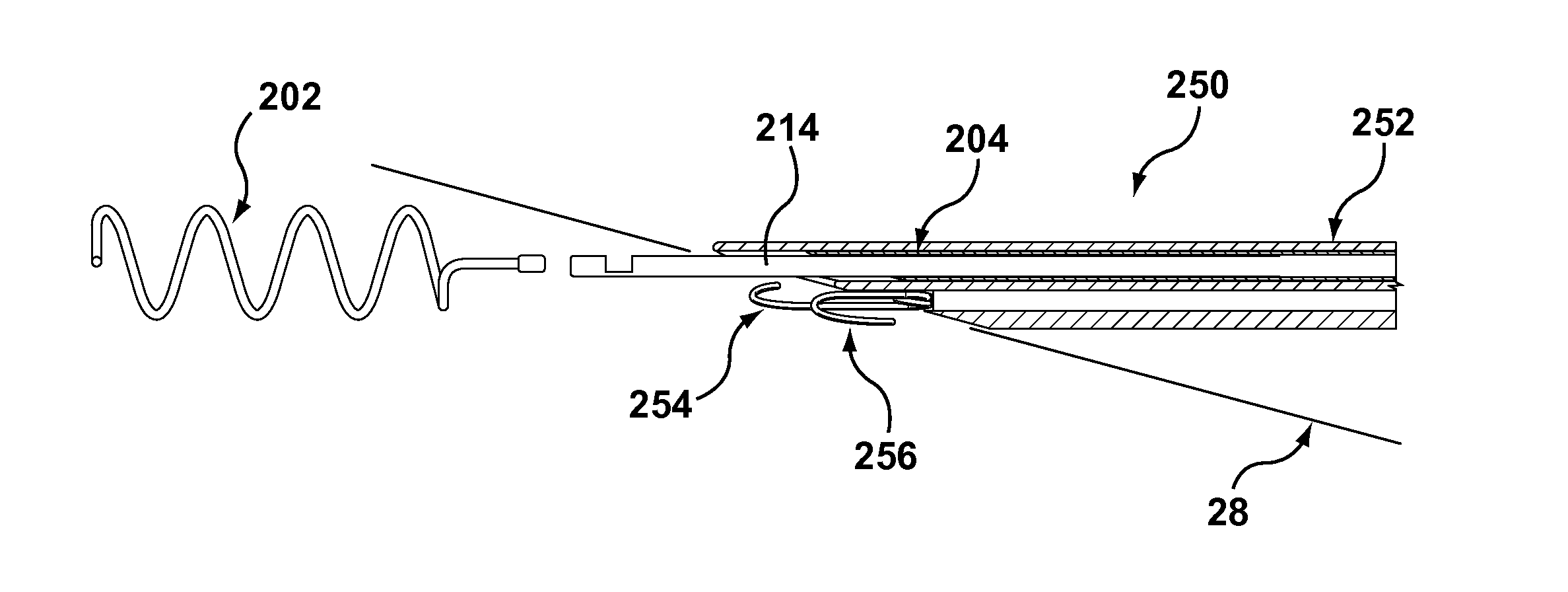
[0010]Embodiments hereof relate to systems and methods for modifying a heart valve annulus in a minimally invasive surgical procedure. A helical anchor is provided, having a memory set to a coiled shape or state. The helical anchor is further configured to self-revert from a substantially straight state to the coiled state. The helical anchor is loaded within a needle that constrains the helical anchor to the substantially straight state. The needle is delivered to the valve annulus and inserted into tissue of the annulus. The helical anchor is then deployed from the needle (e.g., the needle is retracted from over the helical anchor). Once deployed, the helical anchor self-transitions toward the coiled shape, cinching engaged tissue of the valve annulus.

[0011]Other embodiments hereof relate to systems and methods for locating and identifying designated anatomical positions along the valve annulus in a minimally invasive procedure, along with devices, systems and methods for modifyin...


PUM


Abstract

Systems and methods for modifying a heart valve annulus in a minimally invasive surgical procedure. A helical anchor is provided, having a memory set to a coiled shape or state. The helical anchor is further configured to self-revert from a substantially straight state to the coiled state. The helical anchor is loaded within a needle that constrains the helical anchor to the substantially straight state. The needle is delivered to the valve annulus and inserted into tissue of the annulus. The helical anchor is then deployed from the needle (e.g., the needle is retracted from over the helical anchor). Once deployed, the helical anchor self-transitions toward the coiled shape, cinching engaged tissue of the valve annulus.

Description

CROSS-REFERENCE TO RELATED APPLICATIONS[0001]This application claims the benefit of U.S. Appl. No. 61 / 844,507 filed Jul. 10, 2013, which is incorporated by reference herein in its entirety.FIELD OF THE INVENTION[0002]The invention relates generally to the treatment of heart valves. More particularly, it relates to systems, devices, and methods for treating valvular regurgitation, such as mitral regurgitation, via percutaneously delivered helical coils.BACKGROUND OF THE INVENTION[0003]The heart is a four-chambered pump that moves blood efficiently through the vascular system. Blood enters the heart through the vena cava and flows into the right atrium. From the right atrium, blood flows through the tricuspid valve and into the right ventricle, which then contracts and forces blood through the pulmonic valve and into the lungs. Oxygenated blood returns from the lungs and enters the heart through the left atrium and passes through the mitral valve into the left ventricle. The left vent...

Claims


Application Information

Patent Timeline
Patent Type & Authority Applications(United States)
IPC IPC(8): A61F2/24
CPCA61F2/2442A61F2230/0091A61F2/2466A61B17/068A61B2017/00243A61B2017/00331A61B2017/00349A61B2017/00783A61B2017/0649A61F2/2412A61F2002/249
Inventor QUILL, JASONCLAGUE, CYNTHIAGREEN, MICHAELHILL, ALEXANDER J.MENK, ANAROTHSTEIN, PAULBORTLEIN, GEORG
Owner MEDTRONIC INC
Why Eureka
Try Eureka