Method for calibrating analog-controlled hydraulic valves and brake system comprising an electronic control and regulating unit in which the method is carried out

a technology of electronic control and regulating unit, which is applied in the direction of braking system, rotary clutch, fluid coupling, etc., can solve the problems of increasing costs, inability to change over the service life, and increasing costs

Active Publication Date: 2015-01-22
CONTINENTAL TEVES AG & CO OHG
View PDF9 Cites 18 Cited by
  • Summary
  • Abstract
  • Description
  • Claims
  • Application Information

AI Technical Summary

Benefits of technology

[0009]One advantage of the invention is that the relationship between the valve control variable and pressure and, if appropriate, volume flow (control characteristic) can be determined by the brake system itself for each analogized or analog-controlled inlet and outlet valve, for which purpose no wheel brake pressure sensors but just one pressure sensor assigned to the pressure supply device is required. With the aid of the individual control characteristics determined for the individual valves, fine and largely silent wheel-specific pressure control is then possible, and it is possible to dispense with wheel brake pressure sensors for pressure control.
[0010]The brake system preferably comprises one analogized or analog-controlled inlet valve for each wheel brake. As a particularly preferred option, the inlet valves allow the respective brake circuit pressures through in the unactivated state (open when deenergized).
[0011]It is furthermore preferred that there should be one analogized or analog-controlled outlet valve for each wheel brake. As a particularly preferred option, the outlet valves are in a blocked state in the unactivated state (closed when deenergized). However, the method according to the invention can also be carried out in a brake system with “multiplex” inlet valves (i.e. outlet valves can be absent).
[0012]In brake systems in which some of the inlet and / or outlet valves can be controlled in an analog manner and the others can be controlled digitally, the method according to the invention is preferably carried out for all the valves capable of analog control.
[0013]The inlet and outlet valves are preferably embodied as an electromagnetically controllable valves, wherein the electric control variable is an electric current to be fed to the electromagnetic drive.
[0014]Regions of the control characteristic are preferably completed by interpolation or extrapolation or by means of a model, in order to determine the control characteristic between calibration points or in regions without a calibration point. Thus, only a small number of calibration points need be determined. To ensure that the complete control characteristic can be evaluated quickly, the completed control characteristic is particularly preferably stored in the control and regulating unit, e.g. in the form of a table of values.

Problems solved by technology

To configure the production of the AD valves in such a way that each valve exhibits identical control characteristics (e.g. current / pressure characteristic curve), is not possible owing to tolerances or represents an unacceptable expense.
Even if this were possible, change over the service life represents a further problem.
Calibrating each valve individually is very time-consuming in production and increases costs considerably.
However, without being able to operate the valves with appropriate accuracy, functional utility decreases.

Method used


Image

  • Method for calibrating analog-controlled hydraulic valves and brake system comprising an electronic control and regulating unit in which the method is carried out
  • Method for calibrating analog-controlled hydraulic valves and brake system comprising an electronic control and regulating unit in which the method is carried out
  • Method for calibrating analog-controlled hydraulic valves and brake system comprising an electronic control and regulating unit in which the method is carried out

Examples


Embodiment Construction

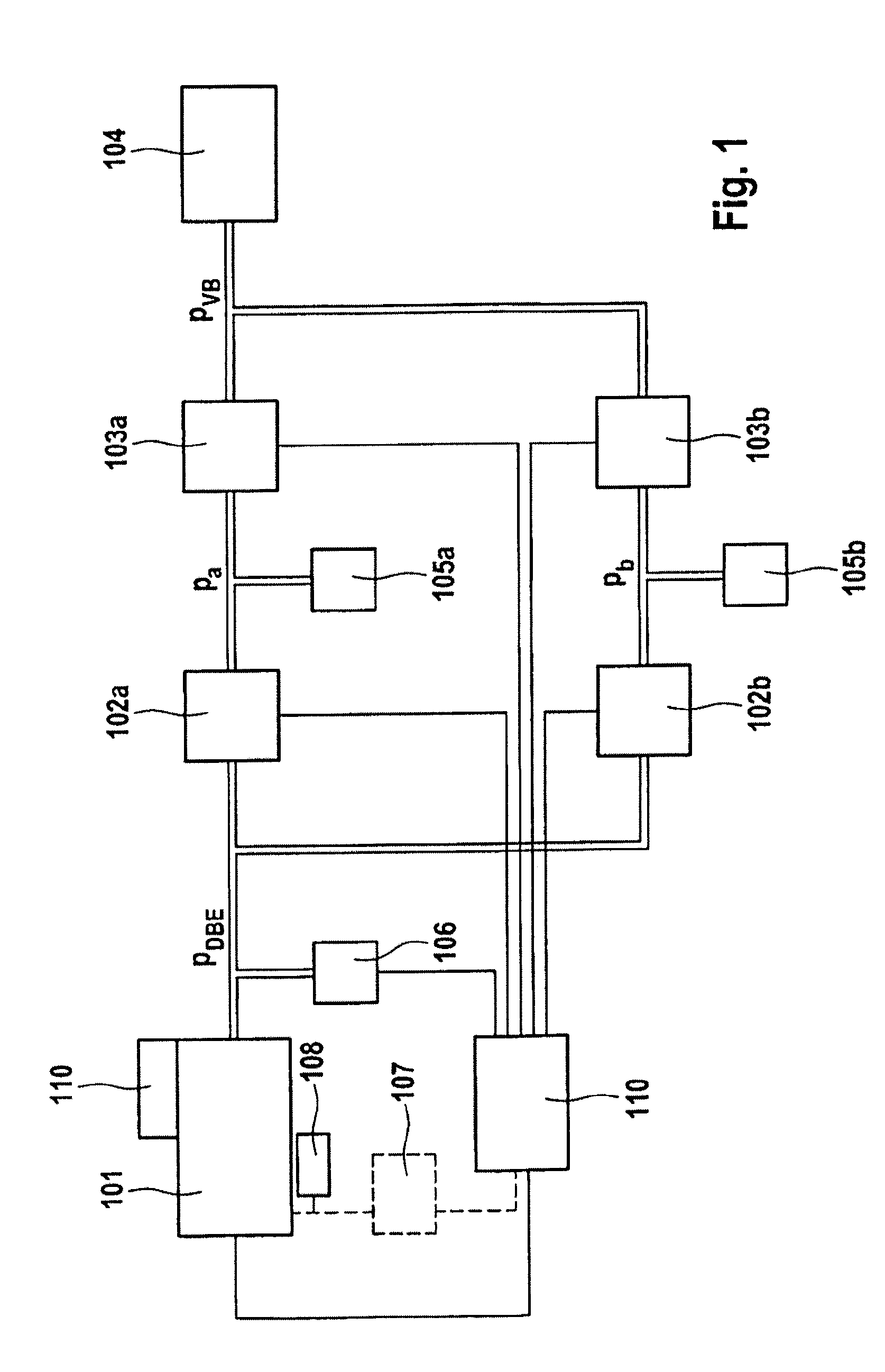
[0050]FIG. 1 shows a block diagram of an illustrative hydraulic brake system for carrying out a method according to the invention. The brake system comprises an electrically controllable, electric-motor-driven pressure supply device 101 for supplying hydraulically actuable wheel brakes 105a, 105b with a pressure pDBE. For this purpose, each wheel brake 105a, 105b is connected or can be connected hydraulically to the pressure supply device 101 via an inlet valve 102a, 102b. The pressure pDBE produced by the pressure supply device 101 is determined by means of a pressure detection device 106 (pressure sensor), which is arranged in the hydraulic connection between the pressure supply device 101 and the inlet valves 102a, 102b. The brake system furthermore comprises at least one pressure medium reservoir 104, e.g. a pressure medium reservoir under atmospheric pressure, to which the wheel brakes 105a, 105b are connected via a respective outlet valve 103a, 103b, allowing pressure medium t...


PUM


Abstract

A method for determining a driving characteristic of an analogized or analog-controlled hydraulic valve of a motor vehicle hydraulic brake system in which a brake pressure generated with the aid of an electrically controllable, electric-motor-driven pressure supply device, is conducted to a wheel brake via an inlet valve and can be conducted via an outlet valve from the wheel brake into a pressure medium container. The pressure supply device and the inlet valves, and outlet valves, can be controlled by an electronic control unit. For determining the control characteristic of an analogized or analog-controlled inlet or outlet valve, a brake pressure is generated by the control unit via the pressure supply device, and the brake pressure is determined by a pressure sensor associated with the pressure supply device. The determined brake pressure and an associated valve control variable are stored as a calibration point of the control characteristic.

Description

CROSS REFERENCE TO RELATED APPLICATIONS[0001]This application is the U.S. National Phase Application of PCT / EP2013 / 054364, filed Mar. 5, 2013, which claims priority to German Patent Application No. 10 2012 203 493.5, filed Mar. 6, 2012 and German Patent Application No. 10 2013 203 599.3, filed Mar. 4, 2013, the contents of such application being incorporated by reference herein.FIELD OF THE INVENTION[0002]The invention relates to a method for determining a control characteristic of an analogized or analog-controlled hydraulic valve and to a brake system.BACKGROUND OF THE INVENTION[0003]In brake systems with antilock control systems (ABS) or electronic stability programs (ESP), analogized valves (“AD valves”) are often used to control the hydraulic fluid. The current at which the AD valve opens is heavily dependent on the pressure difference across the valve. In order to be able to control the AD valves, it is necessary, for example, to know the value of this current, which is referr...

Claims


Application Information

Patent Timeline
Patent Type & Authority Applications(United States)
IPC IPC(8): B60T17/22
CPCB60T17/22B60T7/042B60T11/16B60T15/028B60T8/3655B60T11/103B60T8/36B60T8/4081B60T8/172
Inventor FEIGEL, HANS-JORGBILLER, HARALDHOFFMANN, JANCOURTH, CHRISTIAN
Owner CONTINENTAL TEVES AG & CO OHG
Why Eureka
Try Eureka