Device for Straightening a Flow for Cooling a Roll or a Metal Strip

a technology of straightening and rolling, which is applied in the direction of work cooling devices, metal rolling arrangements, manufacturing tools, etc., can solve the problems of poor heat transmission rate per unit of volume to the applied cooling medium, large amount of cooling medium lost for subsequent processes, and may not be treated at a great cost, so as to achieve a straightening and accelerating stream effect, easy calculation or permit, and easy production

Active Publication Date: 2015-01-22
SMS GRP GMBH
View PDF7 Cites 7 Cited by
  • Summary
  • Abstract
  • Description
  • Claims
  • Application Information

AI Technical Summary

Benefits of technology

[0020]According to a further embodiment, the hollow body and likewise the tube have transverse to the width direction of the roll or the metal strip, a triangular cross-section, and the outlets of the hollow body each is provided essentially at a tip of its triangular cross-section. Such shape of the hollow body or the tube can be easily produced and is extremely effective for obtaining a straightened and accelerating stream.
[0021]The distance between the inner wall of the hollow body extending in the direction of the outlet and the outer wall of the tube located opposite the inner wall advantageously diminishes in the flow direction of the cooling medium or downwardly. Further, such shape facilitates calculatio...

Problems solved by technology

The drawback of this, among others, is the use of a large amount of cooling medium which either is lost for subsequent processes or is returned back and, possibly, must be treated at a great cost.
A further drawback consists in a poor heat transmission rate per unit of volume to the applied cooling medium.
Also, a controlled and varied degree of cooling in the width direction of the roll or strip is not possible with many known devices.
The drawback of such constructions consists in that water is not applied to the metal trip in a controlled manner.
The relative speed between the cooling water and the metal st...

Method used


Image

  • Device for Straightening a Flow for Cooling a Roll or a Metal Strip
  • Device for Straightening a Flow for Cooling a Roll or a Metal Strip
  • Device for Straightening a Flow for Cooling a Roll or a Metal Strip

Examples


Embodiment Construction

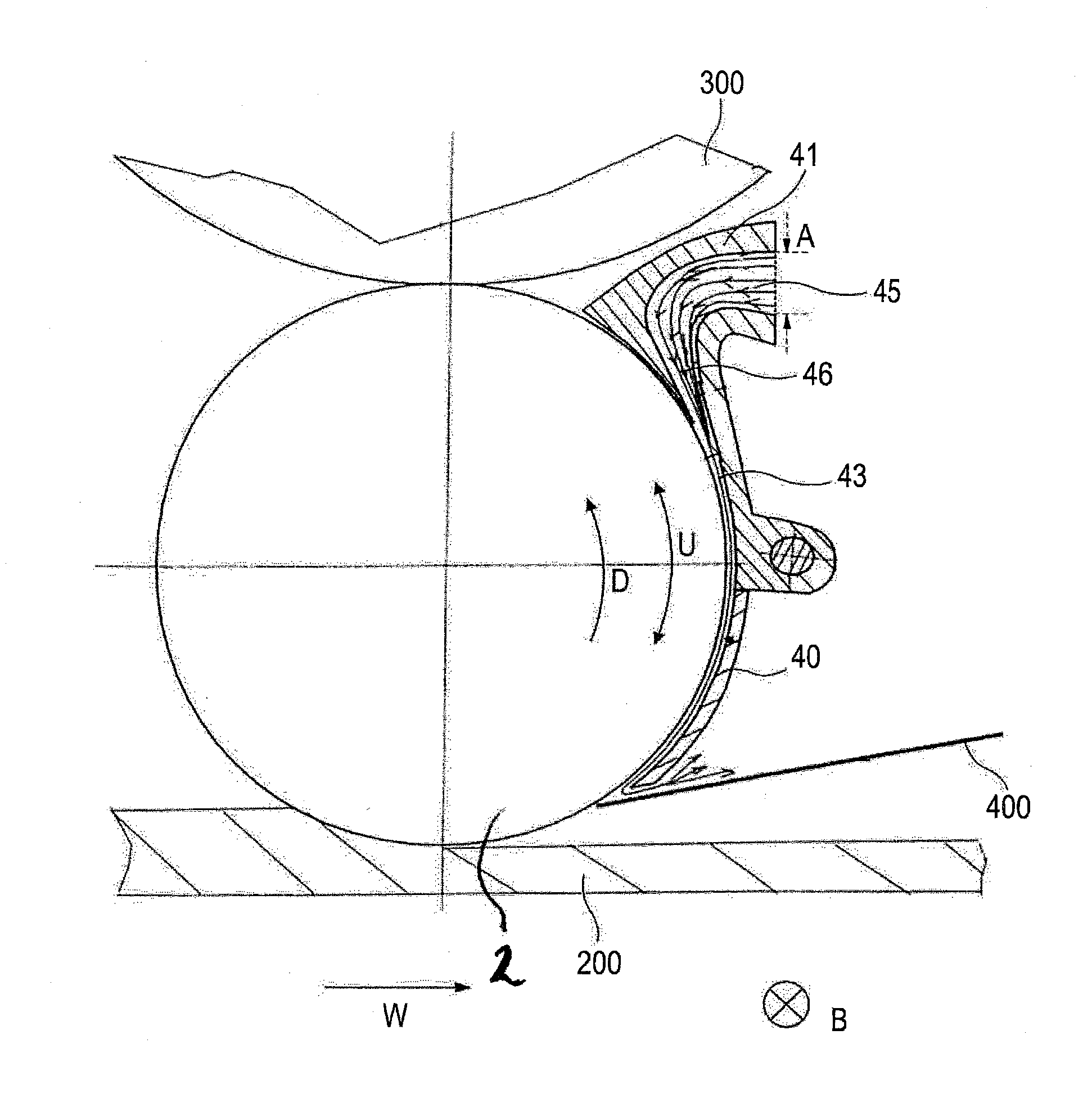
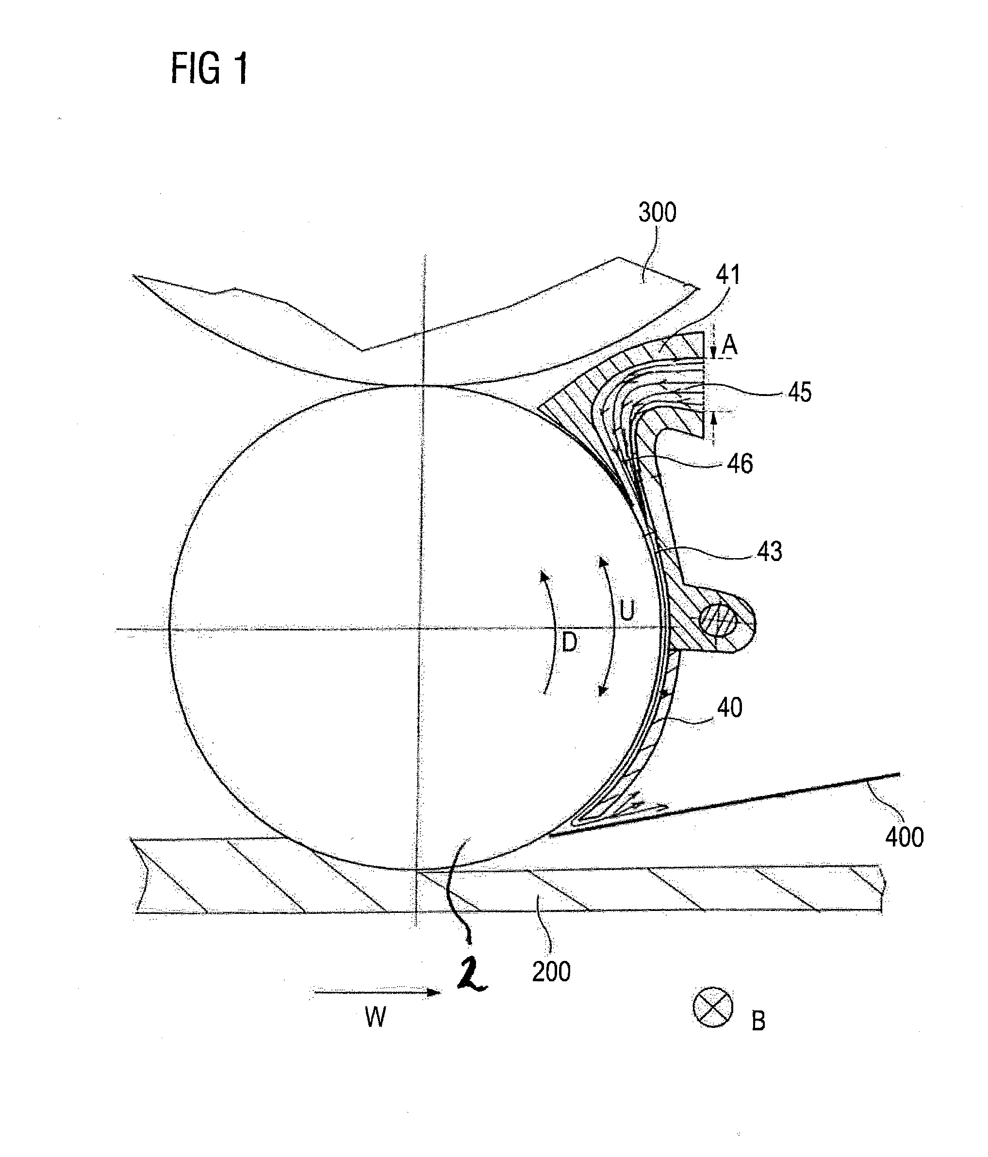
[0041]FIG. 1 shows a portion of the inventive device for cooling a roll 2. The roll 2 can be formed as the shown work roll for rolling a metal strip 200. Such roll 2 can be supported by a backup roll 300 and be cooled, for cooling the roll surface, by cooling medium (such as, e.g., gas, air, water, oil, or by a mixture of these materials). To this end, advantageously, a cooling shell 40 is mounted on a portion of the circumference U of the roll 2. A cooling medium stream can be directed, as shown with stream lines, in the gap 43 between the roll surface and the cooling shell 40 with a nozzle 41. Here, the cooling shell 40 extends at least over a portion of the roll width in the width direction B. The width direction B here extends transverse to the rolling, or casting, or strip displacement direction W. The distance of the cooling shell 40 from the roll surface (the gap height) can be variable or adjustable. To this end, a suitable adjustment device (not shown) can be used, which, e...


PUM

PropertyMeasurementUnit
Lengthaaaaaaaaaa
Widthaaaaaaaaaa

Abstract

The invention is directed to a device for straightening a stream of a cooling medium for cooling a roll or a metal strip. This device comprise a hollow body, extending over at least part of the width of the roll or the metal strip, and a tube, arranged in the hollow body and extending in the direction of the width of the roll or the metal strip, wherein the hollow body is divided in the direction of the width of the roll or the metal strip into a number of chambers, and the tube comprises openings for introducing cooling medium into the chambers of the hollow body, and the chambers respectively comprise an opening for the flowing out of cooling medium from the hollow body. Furthermore, according to the invention the chambers, respectively, comprise a channel, formed between the inner wall of the hollow body and the tube, for conducting cooling medium from the openings of the tube to the opening for the outflow of cooling medium from the hollow body, wherein the flow cross-section of the channel narrows art least at its downstream end.

Description

FIELD OF THE INVENTION[0001]The present invention relates to a device for straightening a stream for cooling a roll or a metal strip or to a straightener. The present invention further relates to a device for cooling a roll or a metal strip.STATE-OF-THE ART[0002]State-of-the art discloses numerous cooling devices for cooling rolls, metal strips or metal sheets wherein, e.g., air, oil emulsion, or water is used.[0003]In some cases, cooling medium is applied simply from cooling medium outlet to to-be-cooled rolls or to-be-cooled strips in large amounts. The drawback of this, among others, is the use of a large amount of cooling medium which either is lost for subsequent processes or is returned back and, possibly, must be treated at a great cost. A further drawback consists in a poor heat transmission rate per unit of volume to the applied cooling medium. Also, a controlled and varied degree of cooling in the width direction of the roll or strip is not possible with many known devices...

Claims


Application Information

Patent Timeline
IPC IPC(8): B21B45/02
CPCB21B45/0218B21B45/0233B21B27/10B21B2027/103
Inventor KIPPING, MATTHIASALKEN, JOHANNESSEIDEL, RALF
Owner SMS GRP GMBH
Why Eureka
Try Eureka