Cutting apparatus

a technology of cutting machine and cutting flange, which is applied in the direction of manufacturing tools, grinding machine components, working accessories, etc., can solve the problems of large torque required to remove the nut and reduce production efficiency, so as to prevent the loosening of the fixing flange, reduce production efficiency, and reduce the effect of large torqu

Active Publication Date: 2015-01-22
DISCO CORP
View PDF5 Cites 9 Cited by
  • Summary
  • Abstract
  • Description
  • Claims
  • Application Information

AI Technical Summary

Benefits of technology

[0006]In general, to prevent the fixing flange from loosening due to the rotation of the spindle in performing the cutting operation, the spiral structure of the screw threads in the support flange and the nut is reverse to the rotational direction of the spindle. Accordingly, as the cutting operation is continued, the nut is firmly tightened to the external screw thread of the support flange without loosening. As a result, in the case of replacing the cutting blade, large torque is required to remove the nut. However, when the cutting blade is worn or chipped, it must be replaced with a new one and this replacement of the cutting blade with respect to the support flange is made relatively frequently. In the conventional mounting structure for the cutting blade, large torque is required to remove the nut as mentioned above, so that there is a problem that the production efficiency may be reduced.

Problems solved by technology

As a result, in the case of replacing the cutting blade, large torque is required to remove the nut.
However, when the cutting blade is worn or chipped, it must be replaced with a new one and this replacement of the cutting blade with respect to the support flange is made relatively frequently.
In the conventional mounting structure for the cutting blade, large torque is required to remove the nut as mentioned above, so that there is a problem that the production efficiency may be reduced.

Method used


Image

  • Cutting apparatus
  • Cutting apparatus
  • Cutting apparatus

Examples


Embodiment Construction

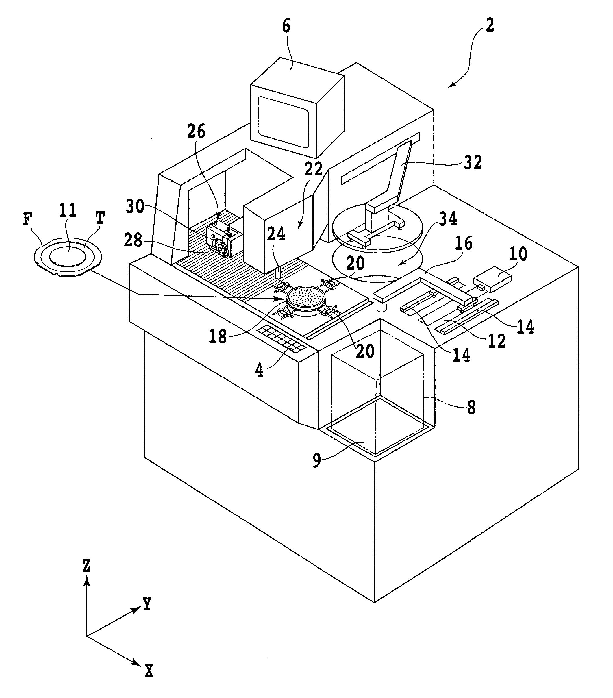
[0018]A preferred embodiment of the present invention will now be described in detail with reference to the drawings. Referring to FIG. 1, there is shown a perspective view of a cutting apparatus 2 including a mounting mechanism for a cutting blade according to this preferred embodiment. The cutting apparatus 2 includes an operation panel 4 for allowing an operator to input instructions such as processing conditions to the apparatus 2. The operation panel 4 is provided at the front portion of the cutting apparatus 2. The cutting apparatus 2 further includes a display unit 6 such as a CRT for displaying a guide view to the operator or an image obtained by an imaging unit to be hereinafter described. The display unit 6 is provided at the upper portion of the cutting apparatus 2.

[0019]A semiconductor wafer (which will be hereinafter referred to also simply as wafer) 11 is a workpiece to be cut by the cutting apparatus 2. The wafer 11 is preliminarily attached to a dicing tape T support...


PUM

PropertyMeasurementUnit
pressure gaugeaaaaaaaaaa
atmospheric pressureaaaaaaaaaa

Abstract

A cutting unit includes a spindle, a spindle housing, a support flange on the front of the spindle, a cutting blade detachably supported to the support flange, and a fixing flange for fixing the cutting blade to the support flange. The support flange includes a boss portion adapted to be inserted through a central opening of the cutting blade, a flange portion for supporting one side surface of the cutting blade, and a cylindrical portion for engaging the front of the spindle. The flange portion has a suction hole opening toward the fixing flange, and the cylindrical portion has a communication hole communicating with the suction hole. The communication hole is connected to a vacuum source through a rotary joint fixed to the spindle housing so that communication between the communication hole and the vacuum source is selectively made by an on-off valve.

Description

BACKGROUND OF THE INVENTION[0001]1. Field of the Invention[0002]The present invention relates to a cutting apparatus for cutting a workpiece such as a semiconductor wafer, and more particularly to a mounting mechanism for a cutting blade in the cutting apparatus.[0003]2. Description of the Related Art[0004]A plurality of devices such as ICs and LSIs are respectively formed in a plurality of separate regions as defined by a plurality of division lines on the front side of a semiconductor wafer. The semiconductor wafer thus having the plural devices is divided into individual device chips by using a cutting apparatus having a cutting blade. The device chips are widely used in various electric equipment such as mobile phones and personal computers. The cutting apparatus includes a chuck table for holding a workpiece, cutting means for cutting the workpiece held on the chuck table, and feeding means for relatively feeding the chuck table and the cutting means, whereby the workpiece such...

Claims


Application Information

Patent Timeline
Patent Type & Authority Applications(United States)
IPC IPC(8): B23B31/30B28D7/04B28D5/02
CPCB23B31/307B28D7/04B28D5/02Y10T83/647B24B27/06B27B5/30B27B5/32B24B45/00B28D5/022
Inventor WAKITA, NOBUHIKO
Owner DISCO CORP
Why Eureka
Try Eureka