Rotating electrical machine armature

a technology for electric machines and armatures, which is applied in the direction of windings, dynamo-electric components, coils, etc., can solve the problems of low space factor of coils, and achieve the effect of accurately winding the first turn, and accurately regular alignmen

Active Publication Date: 2015-01-22
MITSUBISHI ELECTRIC CORP
View PDF6 Cites 5 Cited by
  • Summary
  • Abstract
  • Description
  • Claims
  • Application Information

AI Technical Summary

Benefits of technology

[0023]In the armature for rotary electric machine according to the present invention, in each of all the forward-wound coils and the reversely-wound coils, a part wound on a first side surface of two side surfaces of each tooth that are opposed to the respective adjacent teeth forms a straight portion in which the conductive wires in respective layers of the coil are parallel, and a part wound on a second side surface forms a cross portion in which the conductive wire in an upper layer is wound in a crossed manner on the conductive wire in an adjacent lower layer, and a guide is provided for guiding the conductive wire along a base of a flange of each insulator at a first turn of each coil. Therefore, it becomes possible to accurately wind the first turn of each coil and wind the subsequent turns in an accurately regularly aligned manner.
[0024]The insulator for armature for rotary electric machine according to the present invention is attachable to a tooth, thereby insulting a coil, and has a guide for guiding, along a base of a flange of the insulator, a first turn of a conductive wire where the coil is started to be wound. Therefore, it becomes possible to accurately wind the first turn of each coil and wind the subsequent turns in an accurately regularly aligned manner.
[0025]The coil winding device according to the present invention includes: a holder section for fixing a tooth to which an insulator has been attached, the insulator having a guide for guiding a first turn of a conductive wire where a coil is started to be wound, along a base of a flange; a flyer section for winding the conductive wire on a side surface of the tooth by rotating around the tooth; and a flyer position control section for moving the flyer section in a central axis direction of the tooth just before the conductive wire in an upper layer is wound in a crossed manner on the conductive wire in an adjacent lower layer, on a side surface on which the guide is provided, of the insulator. Therefore, positioning of the cross portion can be accurately performed.
[0026]In addition, it becomes possible to suppress interference between the conductive wires or excessive interference between the conductive wire and the guide, so that the conductive wire can be regularly wound and the quality of the coil can be improved.
[0027]Further, since the cross portion is provided on a side surface opposed to the adjacent tooth, the flyer section can rotate around the tooth at high speed and can perform winding in a regularly aligned manner with high density, and also the productivity of a coil can be improved.
[0028]The coil winding device according to the present invention includes: a holder section for rotating a tooth to which an insulator has been attached, the insulator having a guide for guiding a first turn of a conductive wire where a coil is started to be wound, along a base of a flange, the holder section thereby winding the conductive wire on a side surface of the tooth; and a winding position control section configured to move in a central axis direction of the tooth just before the conductive wire in an upper layer is wound in a crossed manner on the conductive wire in an adjacent lower layer, on a side surface on which the guide is provided, of the insulator. Therefore, positioning of the cross portion can be accurately performed.

Problems solved by technology

However, the space factor of coil is low because conductive wires overlap at the cross portion of coils.

Method used


Image

  • Rotating electrical machine armature
  • Rotating electrical machine armature
  • Rotating electrical machine armature

Examples


embodiment 1

[0045]Hereinafter, an armature for rotary electric machine and an insulator therefor according to embodiment 1 of the present invention will be described with reference to the drawings.

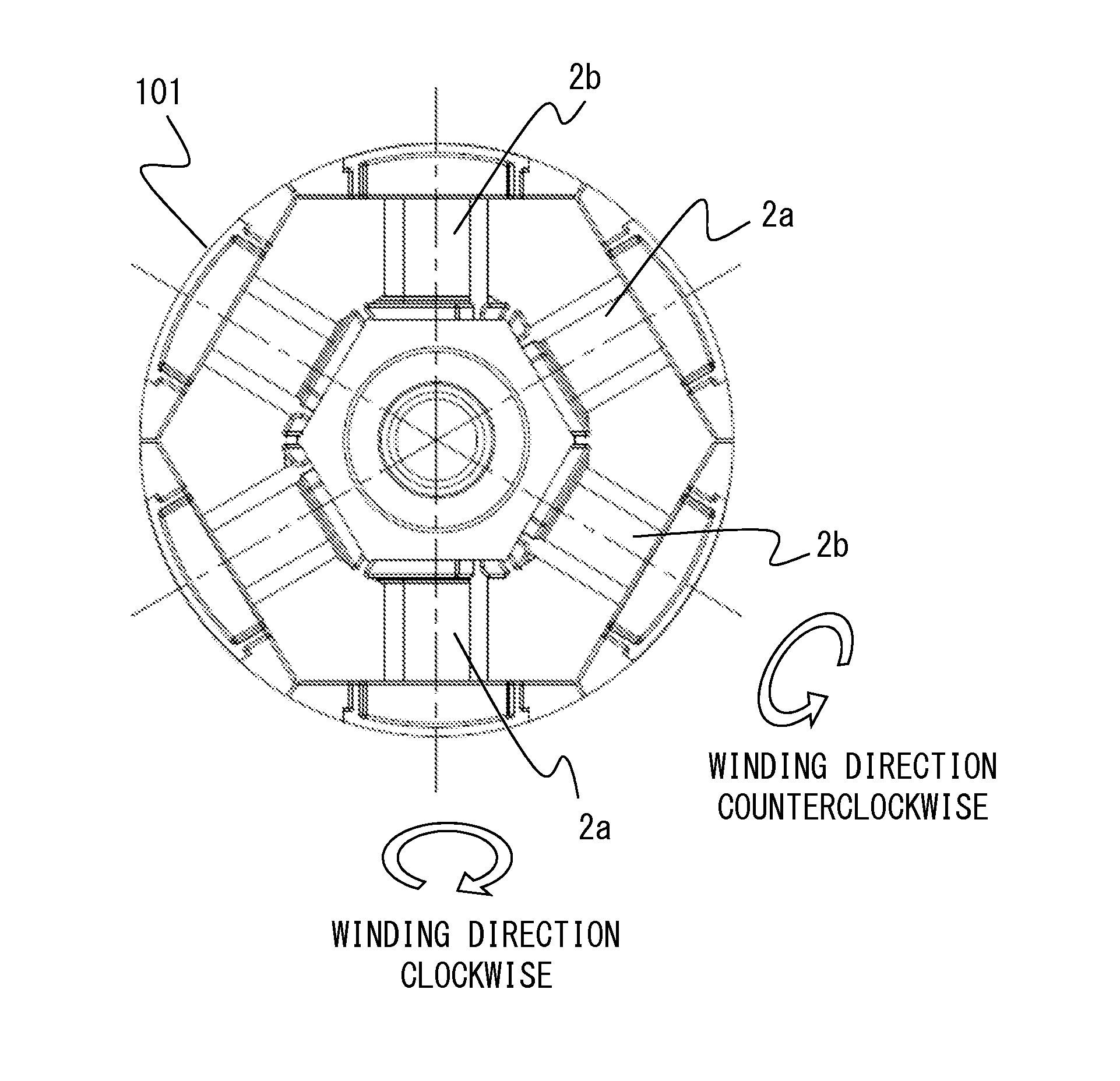
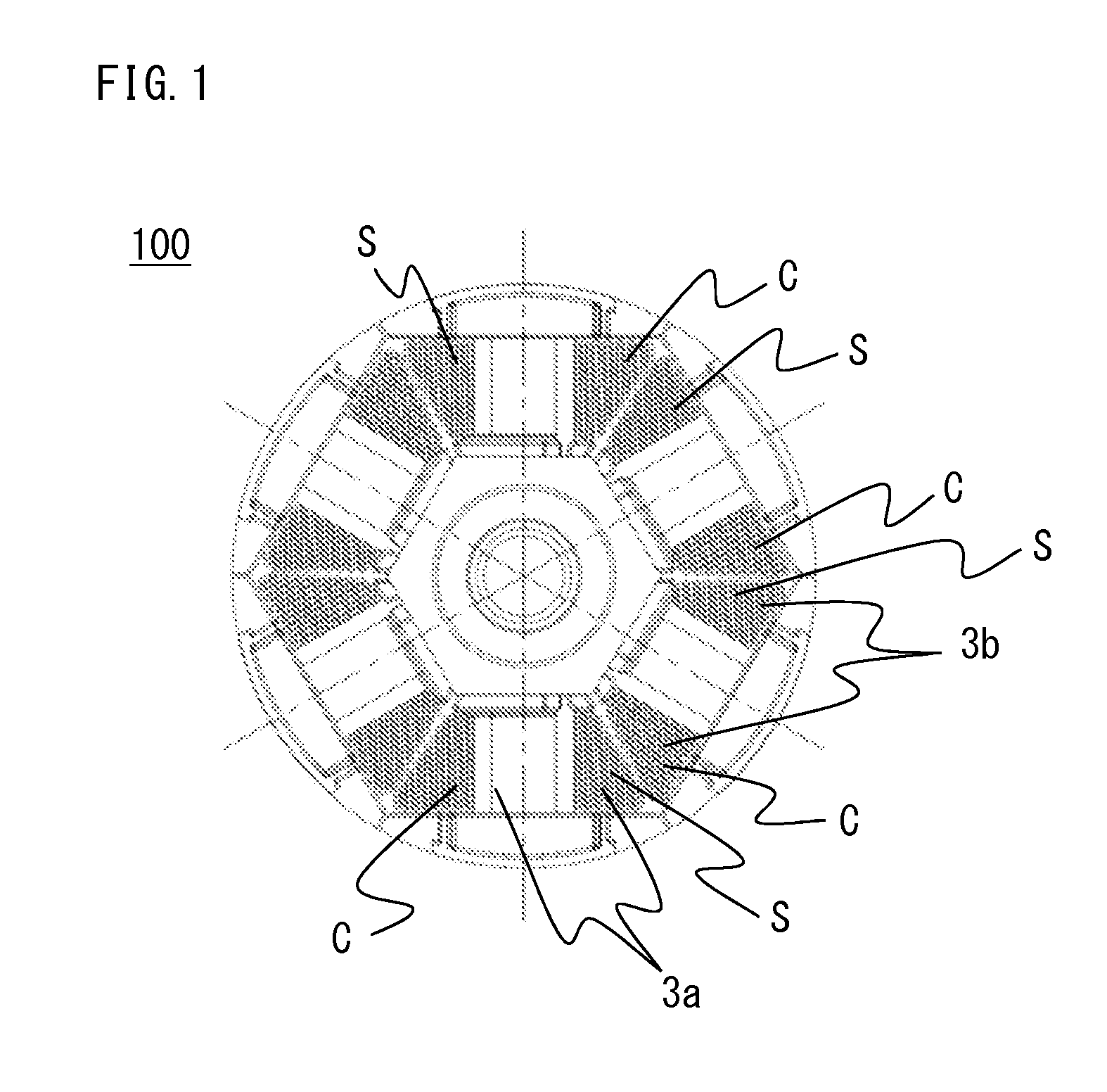
[0046]FIG. 1 is a front view of an armature 100 for rotary electric machine.

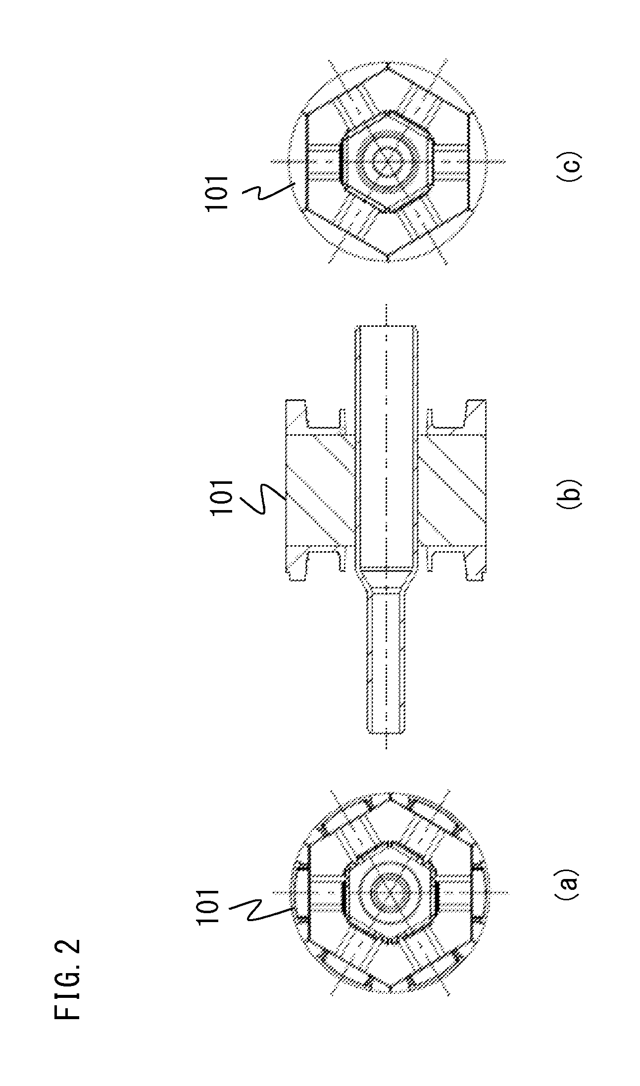
[0047]FIG. 2(a) is a front view of a tooth assembly 101 of the armature 100.

[0048]FIG. 2(b) is a sectional view of the tooth assembly 101 of the armature 100.

[0049]FIG. 2(c) is a back view of the tooth assembly 101 of the armature 100.

[0050]FIG. 3 is an enlarged view of FIG. 2(a).

[0051]FIG. 4 is a perspective view of a clockwise-winding insulator 2a attached to a tooth of an iron core 1 as seen from two directions.

[0052]FIG. 6 is a perspective view of a counterclockwise-winding insulator 2b attached to a tooth of the iron core 1 as seen from two directions.

[0053]As shown in FIG. 3, the tooth assembly 101 of the armature 100 which is a rotor is formed by attaching the clockwise-winding insulator 2a and the counterclockwise-wind...

embodiment 2

[0112]Hereinafter, a cross guide provided on an insulator of an armature for rotary electric machine according to embodiment 2 of the present invention will be described with reference to the drawings.

[0113]FIG. 10 is a view showing a major part of a left side surface 222a of a clockwise-winding insulator 202a attached to a tooth of an iron core of the armature for rotary electric machine according to embodiment 2 of the present invention.

[0114]In embodiment 1, the cross guides 25a and 25b have the same width as the outer diameter of the conductive wire 4.

[0115]In the present embodiment, a cross guide 225a is formed such that the width at the end of the left side surface, that is closest to the upper surface of a tooth is the same as the outer diameter of the conductive wire 4, and the shape is gradually tapered as approaching to the lower side, so as to fill a space between the conductive wire 4 to be obliquely wound and an inner flange 223a.

[0116]The first turn of a coil to be ob...

embodiment 3

[0118]Hereinafter, an armature 300 for rotary electric machine according to embodiment 3 of the present invention will be described with reference to the drawings.

[0119]FIG. 11 is a front view of the armature 300 which is a stator.

[0120]The configuration of the present invention is effective to a coil in the case where a cross portion is accurately formed, and this applies whether the type of armature is a rotor or a stator.

[0121]In the case of stator, the configuration is the same as in embodiment 1, except that the first turn of coil starts from the outer circumferential side of each tooth.

[0122]It is noted that as shown in FIGS. 1 and 11, the present invention is applicable to a rotor or a stator of an armature.

[0123]Particularly, in the case of a rotor or a stator having an even number of teeth on which coils formed by a conductive wire being forward wound in a concentrated manner and coils formed by a conductive wire being reversely wound in a concentrated manner are alternatel...


PUM


Abstract

Provided are an armature for rotary electric machine, an insulator therefor, and a coil winding device for winding a conductive wire on a tooth to which the insulator has been attached, wherein in each of all forward-wound coils and reversely-wound coils, a part wound on a first side surface of two side surfaces of each tooth that are opposed to the respective adjacent teeth forms a straight portion in which conductive wires in respective layers of the coil are parallel, a part wound on a second side surface forms a cross portion in which the conductive wire in an upper layer is wound in a crossed manner on the conductive wire in an adjacent lower layer, and an insulator has a guide for guiding the conductive wire along a base of an inner flange of the insulator at a first turn of each coil.

Description

TECHNICAL FIELD[0001]The present invention relates to an armature for rotary electric machine, an insulator therefor, and a coil winding device.BACKGROUND ART[0002]Conventionally, as a coil configuration for an armature for rotary electric machine, a configuration is proposed in which a portion where a coil in a lower layer and a coil in an upper layer that are adjacent are wound in a crossed manner is located on side surfaces of each tooth, that are opposed to the adjacent teeth.[0003]In this configuration, on such side surfaces opposed to the adjacent teeth, a coil is wound with feed by ½ pitch of the wire diameter, thereby forming a cross portion.[0004]Thus, cross portions are located on two side surfaces of each tooth opposed to side surfaces of the adjacent teeth so that the coil shape becomes substantially a symmetrical shape, thereby obtaining a coil that is excellent in terms of assembly workability, outer appearance, and high-speed winding (for example, Patent Document 1).[...

Claims


Application Information

Patent Timeline
Patent Type & Authority Applications(United States)
IPC IPC(8): H02K3/34H02K3/28
CPCH02K3/345H02K3/28H02K3/52H02K3/18H02K2203/12H02K15/095H02K3/46H01F5/02H01F5/00
Inventor OKA, KEIICHIROAKITA, HIROYUKIYAMAOKA, KUNIHIRO
Owner MITSUBISHI ELECTRIC CORP
Why Eureka
Try Eureka