Power source device having standby power-cutoff function, and method for controlling same

a power source device and power-cutting function technology, applied in secondary cell servicing/maintenance, instruments, safety/protection circuits, etc., can solve the problems of wasting unnecessary power, corresponding standby power waste, and large size of connection units, so as to prevent energy was

Active Publication Date: 2015-01-22
MILPROS CO LTD
View PDF6 Cites 17 Cited by
  • Summary
  • Abstract
  • Description
  • Claims
  • Application Information

AI Technical Summary

Benefits of technology

[0011]According to the present invention, electric power is automatically supplied to a power source device such that the power source device is operated to supply charging power as long as a smartphone is connected to the power source device directly using a micro USB connector, which is an international standard, and if a battery of the smartphone is fully charged or the power source device is separated from the smartphone, the state is detected through a current to automatically cut off electric power of the power source device, whereby standby power of the power source device can be conveniently cut off even though the user does not separate the power source device from a receptacle. Accordingly, waste of energy can be prevented by efficiently completely cutting off standby power which has been wasted according to the related art.

Problems solved by technology

In recent years, effective cutoff of standby electric power is becoming one of the most important problems in increasing energy efficiency of various electronic devices.
Accordingly, corresponding standby power is wasted, and economic loss is nationally caused to produce electric power unnecessarily wasted in this way and carbon dioxide is consistently generated due to use of fossil fuels, which may ultimately cause various problems such as environmental contamination.
According to the related art, if a power source device is separated from a receptacle even though a smartphone is fully charged or separated, standby power is generated in the power source device, wasting unnecessary power.
However, because the patent has a structure in which a switch is connected to supply electric power when a connector is connected to connect an electronic product to a power source device so that it is inevitably necessary to add a mechanical switch, the size of a connection unit becomes large.
In addition, because a switch element is added, manufacturing costs of the product increase.
In addition, in the patent, although a power source device should be connected to an electronic product (for example, a laptop computer or a tablet PC) and a power switch of the electronic product should be switched on to operate an adapter (power source device), the user feel rather inconvenienced because the power source device starts to supply electric power.
Accordingly, although power directly consumed in a receptacle of the power source device can be reduced, wasted electric power cannot be still ignored.

Method used


Image

  • Power source device having standby power-cutoff function, and method for controlling same
  • Power source device having standby power-cutoff function, and method for controlling same
  • Power source device having standby power-cutoff function, and method for controlling same

Examples


embodiments

[0022]A power source device having a function of cutting off standby power and a method of controlling the power source device according to embodiments of the present invention will be described in detail with reference to the accompanying drawings. Names of specific elements such as a smartphone, a backflow prevention part, a power generation part, a driving part, a microprocessor, a battery, a DC / DC converter, a micro USB, a power supply / cutoff part, a current detection part, a CT, a switch, and a cable are referred to in a detailed description of the following specific embodiments, but they are provided to help general understanding of the present invention and the present invention is not limited thereto. It will be appreciated by those skilled in the art to which the present invention pertains that the specific details may be modified or changed by using elements having similar functions as long as they do not depart from the spirit of the present invention defined in the claim...

first embodiment

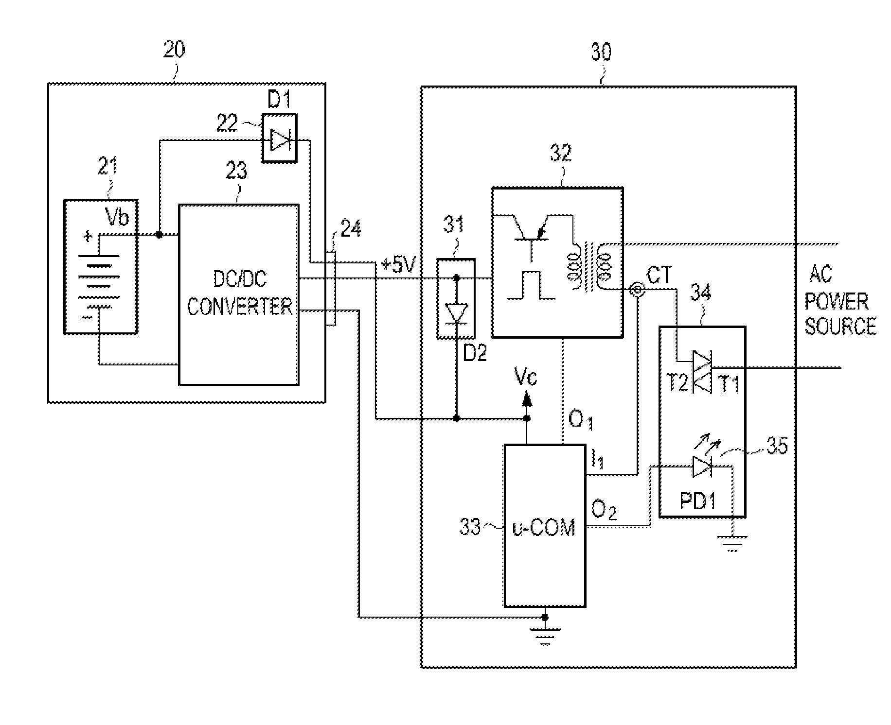
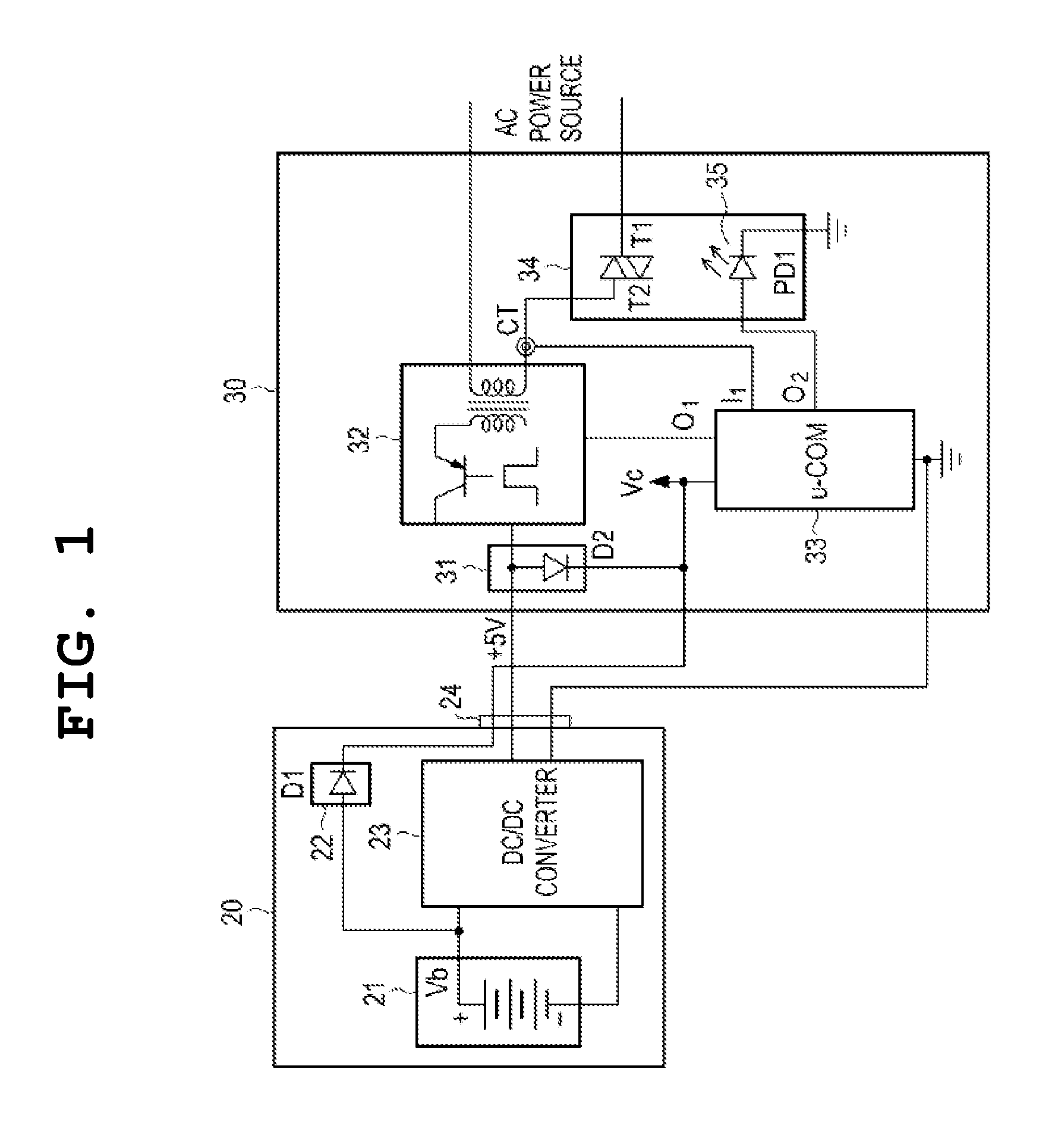
[0024]FIG. 1 is a circuit diagram exemplifying a circuit configuration of a power source apparatus for cutting off standby power and a power source unit of a smartphone according to a first embodiment of the present invention.

[0025]Referring to FIG. 1, a configuration of the present invention will be described as follows. A power source unit 20 of a mobile phone, for example, a smart phone includes a rechargeable battery 21, a DC / DC converter 23 as a unit for providing a charging voltage for charging a battery, and a first backflow prevention unit 22 connected to the battery 21. If the power source unit 20 of a smartphone and a micro USB 24 connector of a power source device 30 are connected to each other, a battery voltage Vb is applied to a microprocessor μ-COM of a control unit 33 to provide a power source voltage for an operation of the power source device 30, and the first backflow prevention unit 22 includes at least one diode D1 in order to prevent DC power from the power sou...

second embodiment

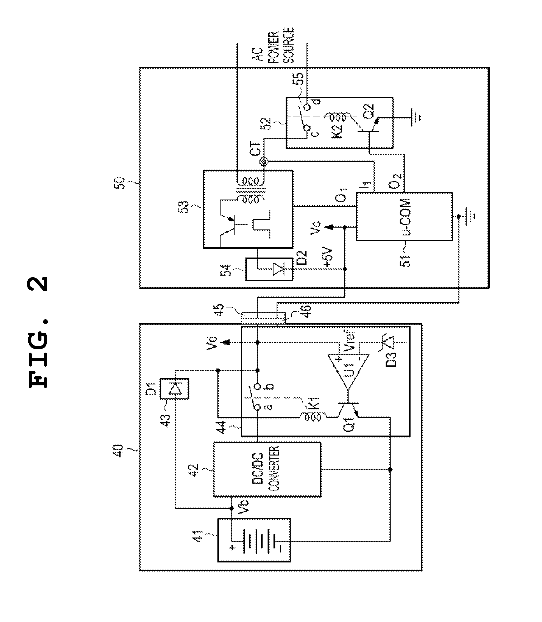
[0034]FIG. 2 is a circuit diagram exemplifying a circuit configuration of a power source device for cutting off standby power and a power source unit of a smartphone according to a second embodiment of the present invention.

[0035]Referring to FIG. 2, a configuration of a power source device according to the second embodiment of the present invention will be described as follows. The power source unit 40 of the smartphone according to the present invention includes a battery 41, a DC / DC converter 42 for supplying a charging voltage to the battery, a charging voltage supply unit 44 for determining whether a supplied voltage is a charging voltage or a battery voltage Vb and supplying or cutting off electric power to the DC / DC converter 42, a first backflow prevention unit 43 for preventing electric power from reversely flowing to the battery when a voltage of +5 V is supplied to a power source device 50, and a micro USB connector 46 for connection to the power source device 50. As show...


PUM


Abstract

Disclosed is a power source device having a standby power-cutoff function, which is to be used to charge a battery. The power source device comprises: a micro-USB connector (24) for connecting to the power source unit (20) of a smartphone when the battery of the smartphone or the like is to be charged; and a power generation unit (32) supplying DC charging power to the smartphone (20) from an AC input power source. The present invention includes: a control unit (33) having at least one microprocessor for controlling the overall operation and functioning of a power source device (30); a power supply/cutoff unit (34) supplying/cutoff the AC input power to the power generation unit (32) according to the control of the control unit (33); and a current-sensing unit (CT) connected so as to monitor the current from the power supply/cutoff unit (34), provide the control unit (33) with the current, and provide an indication of the charging state of the battery. The power source unit (20) of the smartphone also includes a first backflow-preventing unit (22) connected between the battery (21) and the control unit (33) so as to prevent the DC power from the power source device (30) from being directly applied to the battery (21) during charging, and the power source device (30) further includes a second backflow-preventing unit (31) which is connected between the DC charging voltage output terminal of the power generation unit (32) and the power supply voltage (Vc) of the control unit (33).

Description

CROSS-REFERENCE TO RELATED APPLICATIONS[0001]This application is a continuation of International Application No. PCT / KR2013 / 002965 filed on Apr. 9, 2013, which claims priority to Korean Patent Application No. 10-2012-0036490 filed on Apr. 9, 2012 and Korean Application No. 10-2012-0041238 filed on Apr. 20, 2012. The applications are incorporated herein by reference.TECHNICAL FIELD[0002]The present invention relates to a power source device for supplying electric power for charging an electronic product such as a mobile phone and smartphone having a battery and a charging device therein, and more particularly to a power source device having a function of automatically completely cutting of standby power even though the power source device is not separated from a receptacle if a battery is fully charged or a product is separated, and a method of controlling the same.BACKGROUND ART[0003]According to recent statistics of the International Energy Agency (IEA), it is known that at least 1...

Claims


Application Information

Patent Timeline
Patent Type & Authority Applications(United States)
IPC IPC(8): H02J7/00
CPCH02J7/007H02J2007/0059H02J2007/0062H01M10/44H02J7/04H02J7/00H01M10/46H01M10/48H02J2207/20H02J7/342Y02E60/10H02J7/0049H02J9/005H02J7/0029H02J7/00712G01R31/382H02J2207/30
Inventor KIM, CHANG-HO
Owner MILPROS CO LTD
Why Eureka
Try Eureka