Profilometer with partial coherence interferometer adapted for avoiding...

a technology of partial coherence and interferometer, applied in the field of measuring systems, can solve problems such as inability to track, measurement could be taken on the wrong side, and shift could occur

Active Publication Date: 2015-01-22
QUALITY VISION INT
View PDF7 Cites 1 Cited by
  • Summary
  • Abstract
  • Description
  • Claims
  • Application Information

AI Technical Summary

Benefits of technology

[0007]The invention further exploits the capabilities of partial coherence interferometers at essentially two different interferometer configurations to resolve the ambiguity between measurements taken on opposite sides of the null position. The configuration of the interferometer is changed by deliberately altering the optical path length difference between the object and reference arms and by monitoring the related change in modulatio

Problems solved by technology

However, a sudden height shift could occur that cannot be track

Method used


Image

  • Profilometer with partial coherence interferometer adapted for avoiding...
  • Profilometer with partial coherence interferometer adapted for avoiding...
  • Profilometer with partial coherence interferometer adapted for avoiding...

Examples


Embodiment Construction

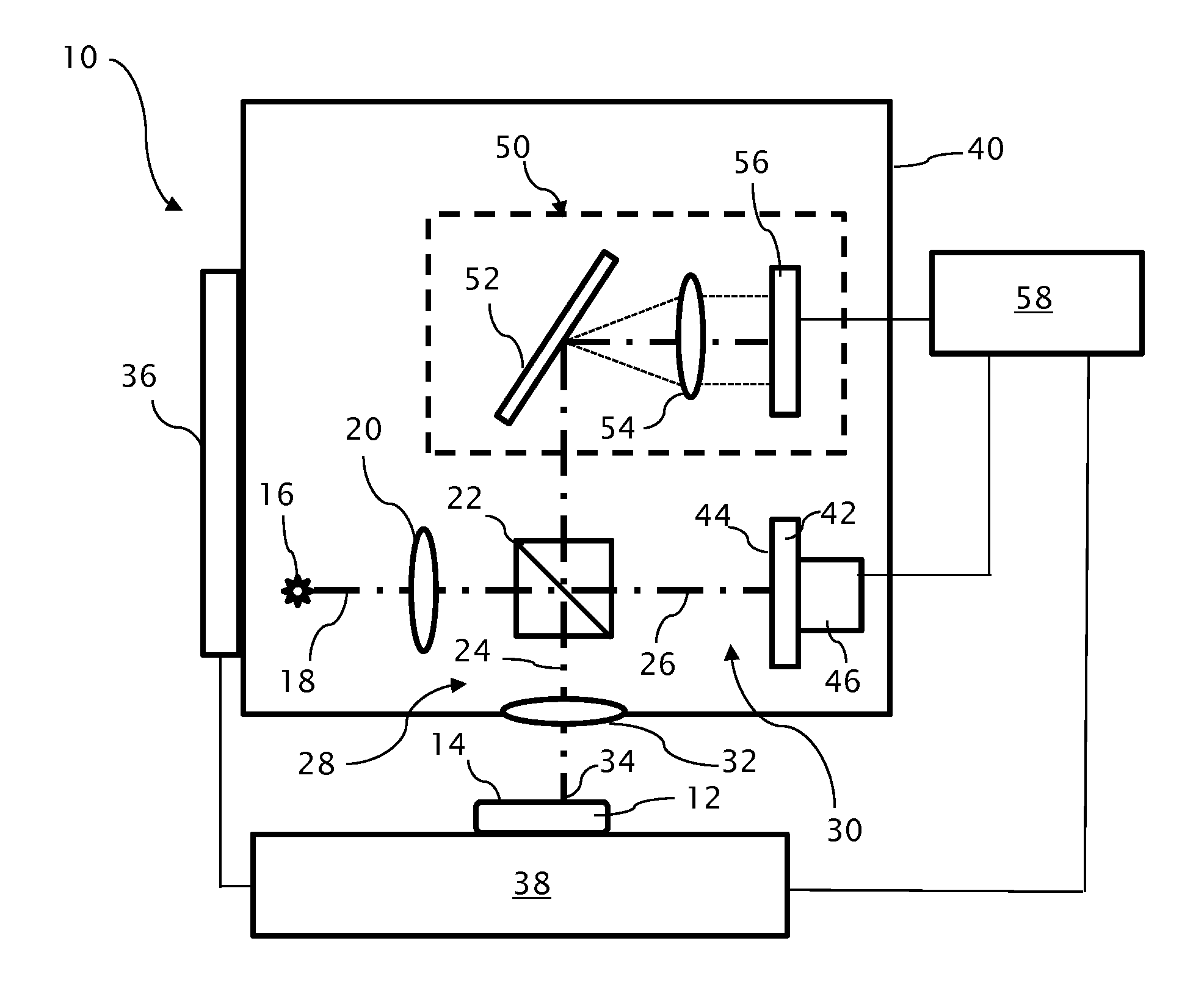
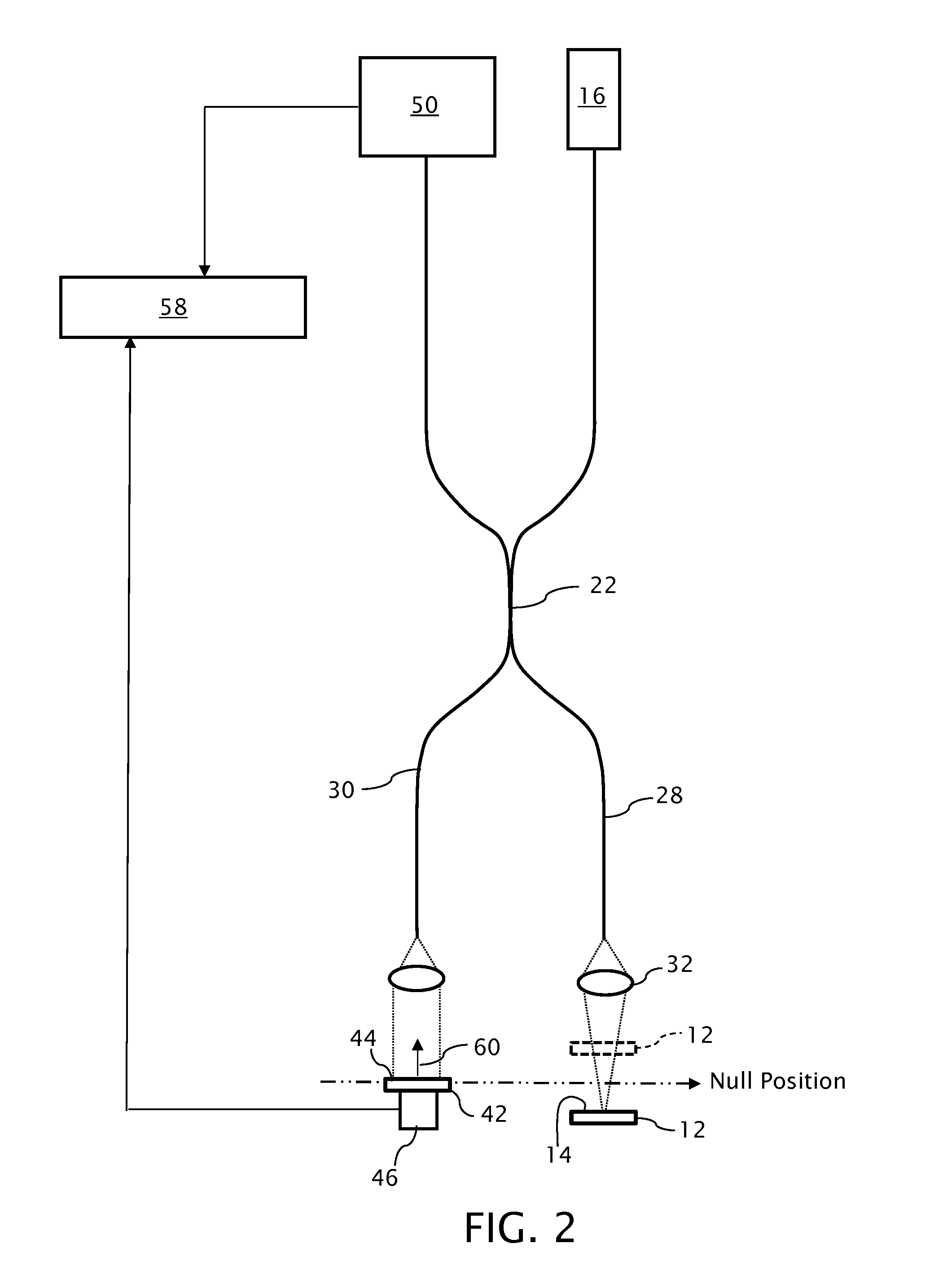
[0025]An optical profilometer 10 incorporating a partial coherence interferometer is shown in FIG. 1 in a configuration for measuring a surface 14 of a test object 12. A light source 16 of the profilometer 10 emits a measuring beam 18 having a given spectral bandwidth, preferably within the visible or infrared spectrum. The light source 16 is preferably a broadband light source 16, such as a superluminescent diode, having power output of approximately 5 milliwatts and a spectral bandwidth of approximately 40 nanometers of wavelength or more at a nominal wavelength of approximately 800 nanometers. As such, the light source 16 can also be referred to as a low temporal coherence source. However, the light source 16 preferably retains spatial coherence so that the measuring beam 18 can be focused to a small spot size for taking individual measurements on the test object surface 14.

[0026]A collector / collimating optic 20 collects light from the light source 16 for further propagating the ...


PUM


Abstract

A profilometer incorporating a partial coherence interferometer directs a beam containing a band of wavelengths along object and reference arms of the interferometer into respective engagements with a test object surface and a reference object surface en route to a spectrometer for measuring a spectrum of the beam. Within the object arm, the test object surface is relatively moved through a range of positions offset from a null position at which optical path lengths of the object and reference arms are equal. Modulation frequencies of the beam spectrum are calculated at a succession of different focus spot positions across the test object surface. Changes in the modulation frequency are interpreted to distinguish between optical path length differences at which the optical path length of the object arm is longer or shorter than the optical path length of the reference arm.
6

Description

TECHNICAL FIELD[0001]The invention relates to measuring systems, including profilometers, particularly of a type incorporating partial coherence interferometers, and to the avoidance of interferometric measurements straddling a null position.BACKGROUND OF THE INVENTION[0002]Optical profilometers include optical probes for taking point-by-point measurements across a test object. The probes typically include a focusing optic to focus light onto a small spot on a test object. The same focusing optic can be used to collect light reflected from the focus spots for purposes of measurement.[0003]Partial coherence interferometers can be used with optical profilometers to interpret depth changes in the focus spot as changes in the surface height of test objects. The light sources of partial coherence interferometers typically produce spatially coherent beams encompassing a band of wavelengths. Object and reference arms of the interferometer convey different portions of the beam into respecti...

Claims


Application Information

Patent Timeline
IPC IPC(8): G01B9/02
CPCG01B9/02091G01B11/2441G01B9/0209G01B9/02071G01B9/02044G01J3/00
Inventor KAY, DAVID, B.
Owner QUALITY VISION INT
Why Eureka
Try Eureka