
Laser-driven optical gyroscope with push-pull modulation

a push-pull modulation, optical gyroscope technology, applied in the direction of speed measurement using gyroscopic effects, instruments, surveying and navigation, etc., can solve the problems of broadband source introduction, parasitic errors, and limit the performance of laser-driven fog far above inertial navigation requirements, so as to reduce coherent backscattering-induced errors

Inactive Publication Date: 2015-01-22
THE BOARD OF TRUSTEES OF THE LELAND STANFORD JUNIOR UNIV
View PDF12 Cites 25 Cited by
  • Summary
  • Abstract
  • Description
  • Claims
  • Application Information

AI Technical Summary

Benefits of technology

The patent describes a method to reduce errors in an optical gyroscope caused by coherent backscattering. The method involves using two laser signals that are phase-modulated in opposite directions and then combined. The resulting signal is transmitted to a detector. The technical effect is to improve the accuracy of the output of the optical gyroscope.

Problems solved by technology

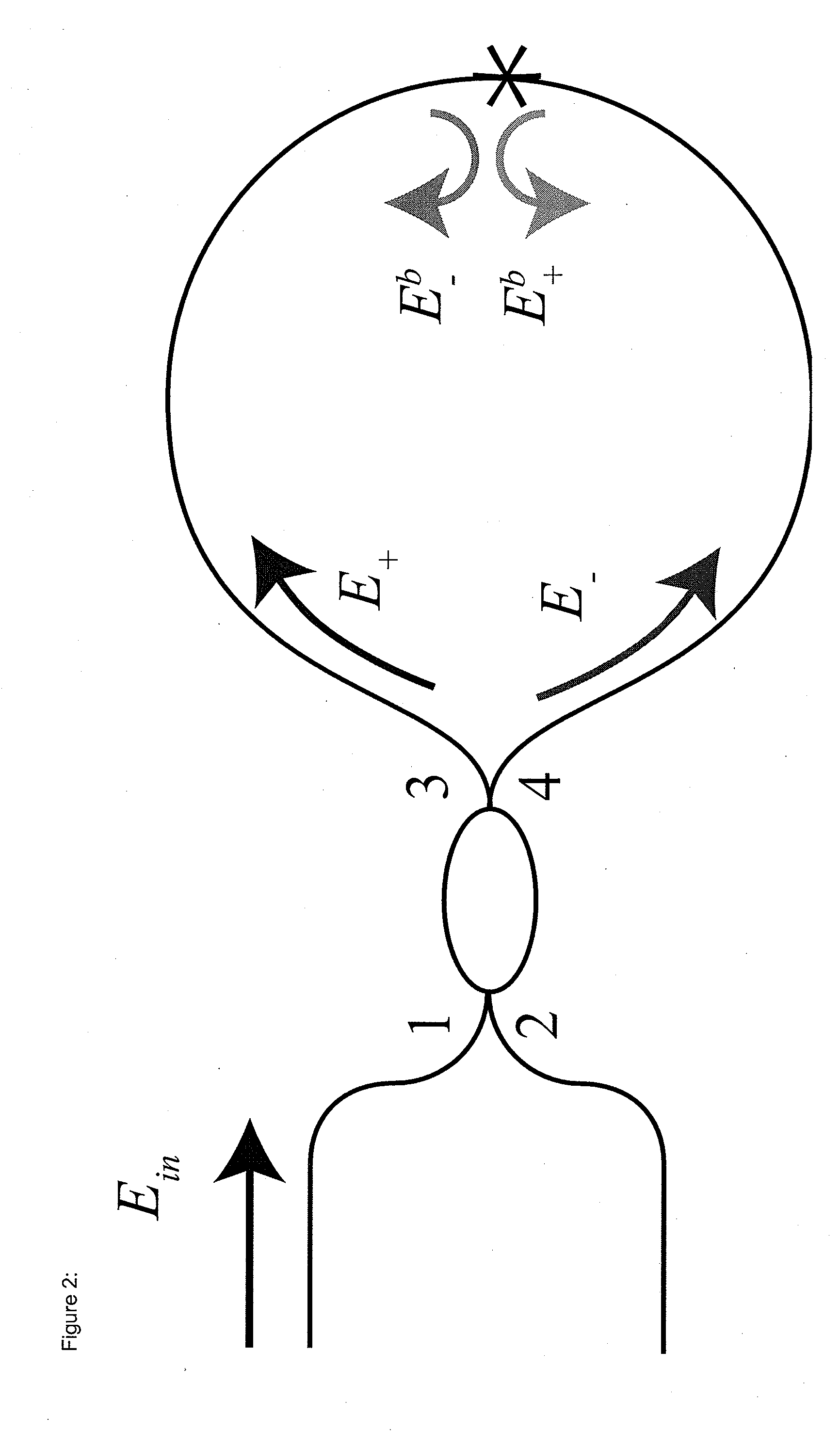
However, these experiments and subsequent analysis showed that using coherent light in a FOG leads to three significant sources of parasitic errors (e.g., noise and drift in the sensor output), namely (1) nonlinearity of the propagation constant, dominated by the Kerr effect (nonlinear Kerr-induced drift), (2) polarization errors (polarization-induced drift) caused by coupling between polarization states within the Sagnac interferometer, which has a significant magnitude because of the finite extinction ratio of the polarizer and polarization-mode degeneracy in single-mode fibers, and (3) backscattering in the sensor path, primarily dominated by distributed Rayleigh scattering (coherent backscattering-induced noise and drift).
Investigations at the time accurately predicted that while a laser-driven gyroscope can provide a good scale factor stability, these three sources of error would limit the performance of a laser-driven FOG far above inertial navigation requirements.
However, a broadband source introduced other issues.
First, broadband sources exhibit excess noise, which is typically much larger than shot noise, hence the FOG's minimum detectable rotation rate has been limited all these years to values much higher than the shot-noise limit.
Second, the mean-wavelength stability of a broadband source is low (typically 10-100 ppm for the Er-doped superfluorescent fiber source (SFS) used in some commercial FOGs), which means that the FOG scale factor, which is inversely proportional to this mean wavelength, is inadequate for high-end applications.
These issues, particularly this last one, have limited the FOG's competitiveness compared with other optical gyros for the enormous market of inertial aircraft navigation.

Method used


Image

  • Laser-driven optical gyroscope with push-pull modulation
  • Laser-driven optical gyroscope with push-pull modulation
  • Laser-driven optical gyroscope with push-pull modulation

Examples


Embodiment Construction

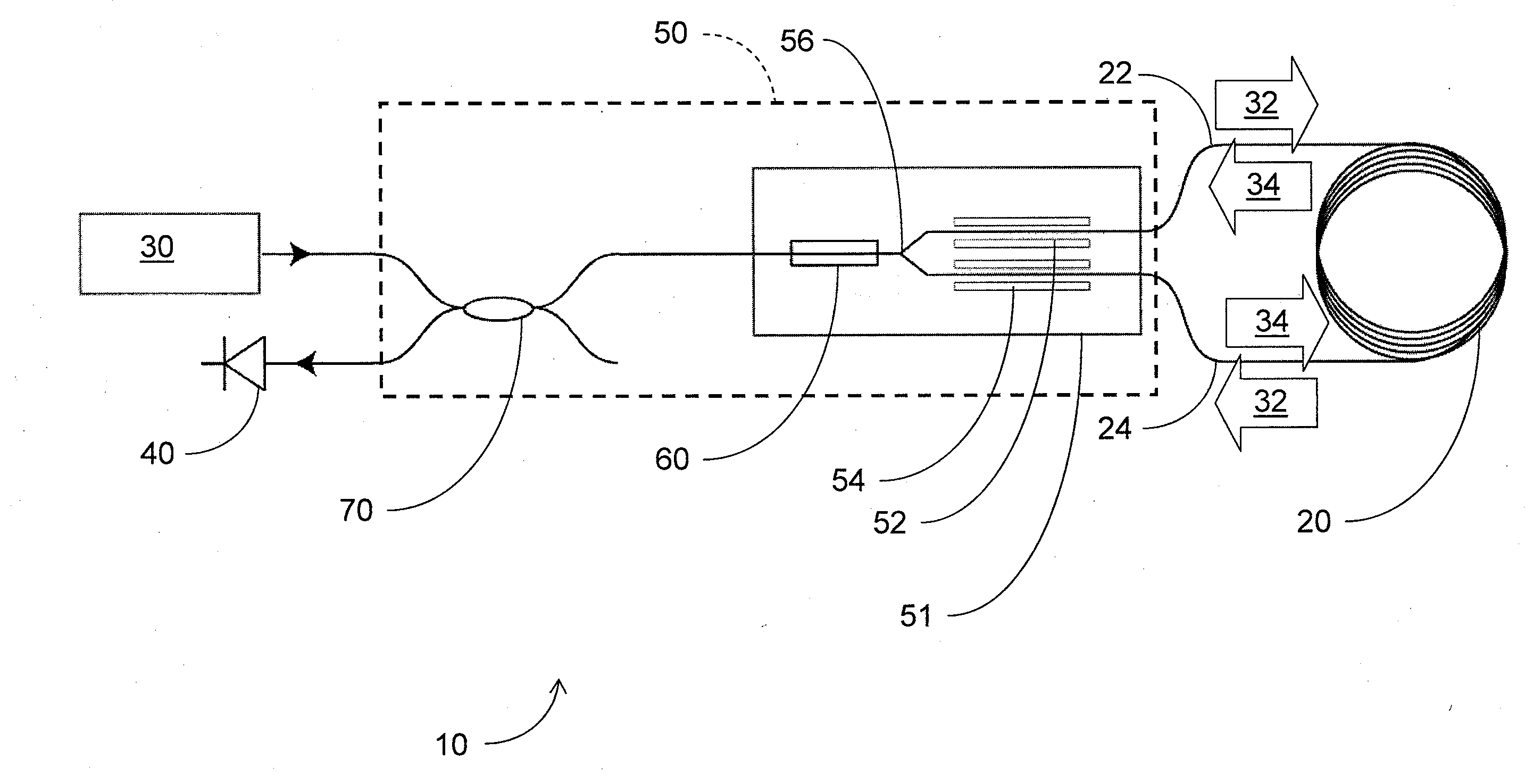
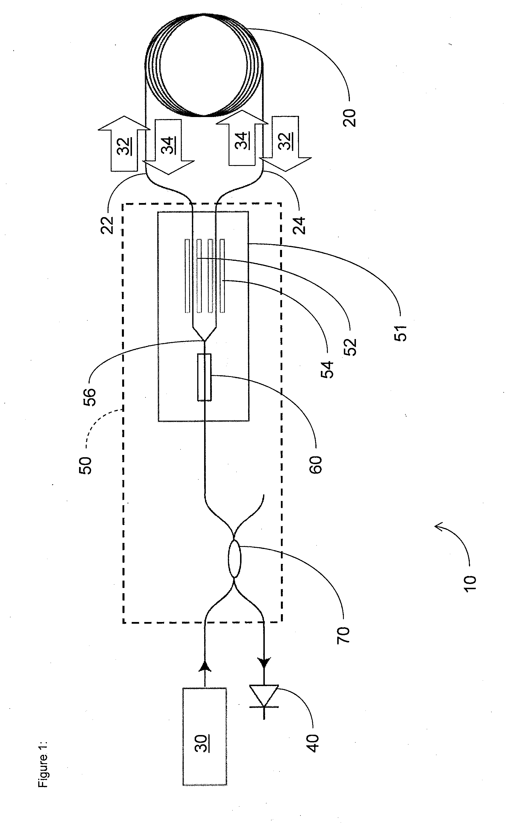
[0021]Based on insights from a new model of scattering in optical gyroscopes, such as fiber optic gyroscopes (FOGs), using high-coherence sources (e.g., laser sources with linewidths less than 108 Hz or less than 1011 Hz), certain embodiments described herein provide an optical gyroscope driven with a laser of suitable linewidth advantageously exhibits short and long-term performance matching and / or exceed that of the same optical gyroscope driven by a broadband source (e.g., source with bandwidth greater than 1011 Hz). In certain embodiments, the optical gyroscope can be combined with the use of a hollow-core fiber in the sensor coil to produce new optical gyroscopes exceeding current standards.

[0022]A laser has two major advantages over broadband sources. Because a semiconductor laser around 1.5 μm has an excellent wavelength stability (typically <1 part per million (ppm)), the issue of scale factor stability would be resolved. A laser also has negligible excess noise compared to ...


PUM


Abstract

A system and method for reducing coherent backscattering-induced errors in an optical gyroscope is provided. A first time-dependent phase modulation is applied to a first laser signal and a second phase modulation is applied to a second laser signal. The phase-modulated first laser signal propagates in a first direction through a waveguide coil and the phase-modulated second laser signal propagates in a second direction opposite the first direction through the waveguide coil. The first time-dependent phase modulation is applied to the phase-modulated second laser signal after the phase-modulated second laser signal propagates through the waveguide coil to produce a twice-phase-modulated second laser signal. The second time-dependent phase modulation is applied to the phase-modulated first laser signal after the phase-modulated first laser signal propagates through the waveguide coil to produce a twice-phase-modulated first laser signal. The twice-phase-modulated first and second laser signals are transmitted to a detector.

Description

CROSS-REFERENCE TO RELATED APPLICATIONS[0001]This application claims the benefit of priority to U.S. Provisional Appl. No. 61 / 657,657, filed Jun. 8, 2012 and incorporated in its entirety by reference herein.BACKGROUND[0002]1. Field of the Application[0003]The present application relates generally to optical gyroscopes, and more specifically, to optical gyroscopes utilizing a laser source.[0004]2. Description of the Related Art[0005]Since the initial theoretical and experimental demonstration of the fiber optic gyroscope (FOG) by Vali and Shorthill in 1976, the fiber-optic gyroscope (FOG) has become the most commercially successful fiber sensor, with several major manufacturers shipping tens of thousands of units annually worldwide. Intense research efforts throughout the 1980s and early 1990s focused on minimizing parasitic errors due to Rayleigh backscattering, the nonlinear Kerr effect, polarization-induced non-reciprocity, Shupe effect, and other lesser sources of error. The deve...

Claims


Application Information

Patent Timeline
Patent Type & Authority Applications(United States)
IPC IPC(8): G01C19/66G01C25/00
CPCG01C25/00G01C19/66G01C19/721G01C19/726
Inventor LLOYD, SETHDIGONNET, MICHEL J.F.FAN, SHANHUI
Owner THE BOARD OF TRUSTEES OF THE LELAND STANFORD JUNIOR UNIV
Learn More