
Apparatus and method for visualizing a conduction tract of heart

a technology of conduction tract and applicator, which is applied in the field of applicator, a computer program and a method of visualizing the conduction tract of the heart, can solve the problems that doctors cannot see the location of the conduction tract either

Active Publication Date: 2015-01-22
KONINKLJIJKE PHILIPS NV
View PDF5 Cites 2 Cited by
  • Summary
  • Abstract
  • Description
  • Claims
  • Application Information

AI Technical Summary

Benefits of technology

The present invention provides an apparatus, method, and computer program for visualizing a conduction tract of the heart using a refined model. This visualization helps in avoiding or finding the conduction tract during a procedure like ablation of heart tissue. The use of a refined model and visualization improves the practitioner's information and reduces risks involved in the procedure. The apparatus uses the refined model to define an area for the active operation of the medical instrument, which limits the risks of the procedure.

Problems solved by technology

However, from such data a physician still cannot see the location of the conduction tracts either.

Method used


Image

  • Apparatus and method for visualizing a conduction tract of heart
  • Apparatus and method for visualizing a conduction tract of heart
  • Apparatus and method for visualizing a conduction tract of heart

Examples


Embodiment Construction

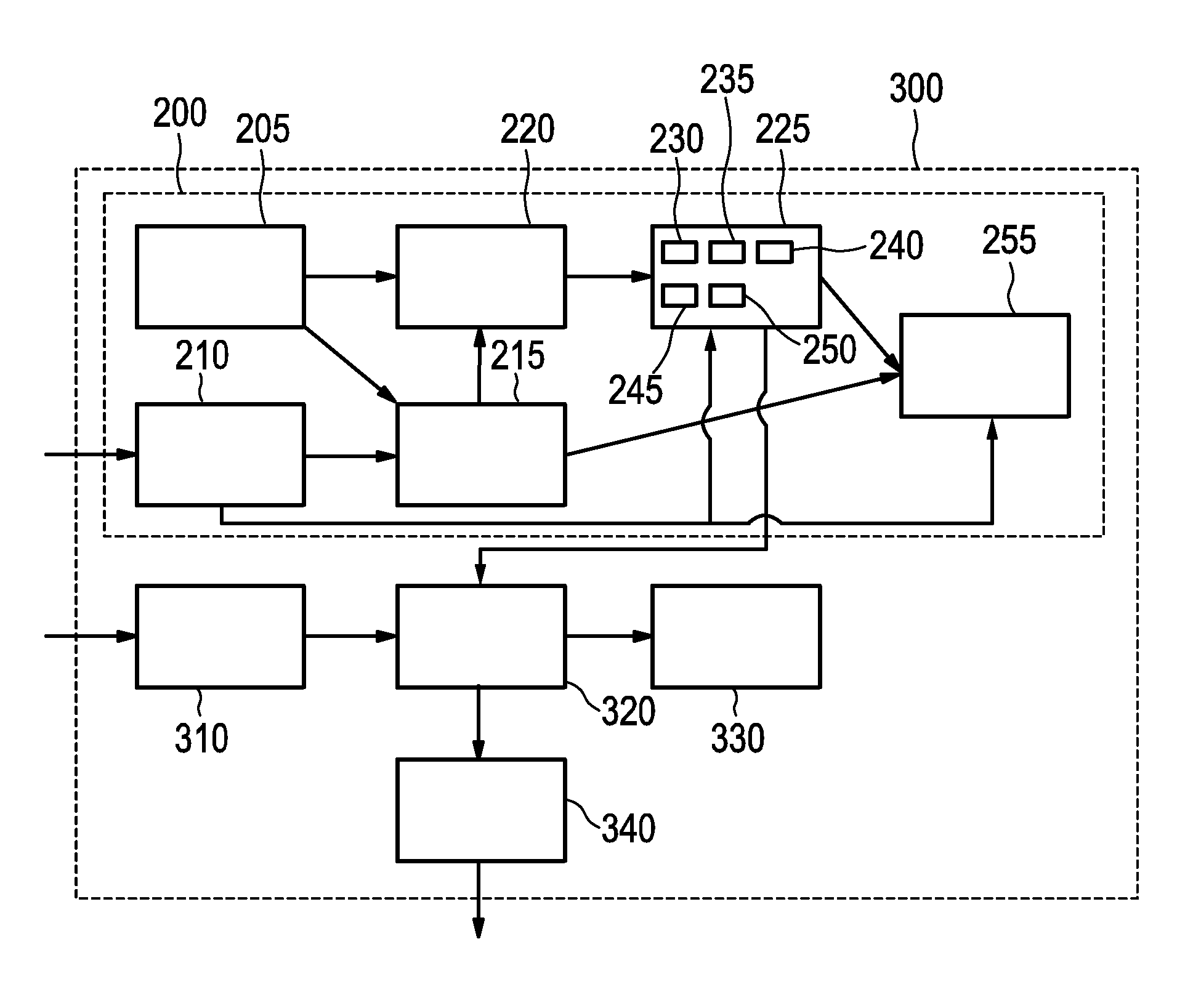
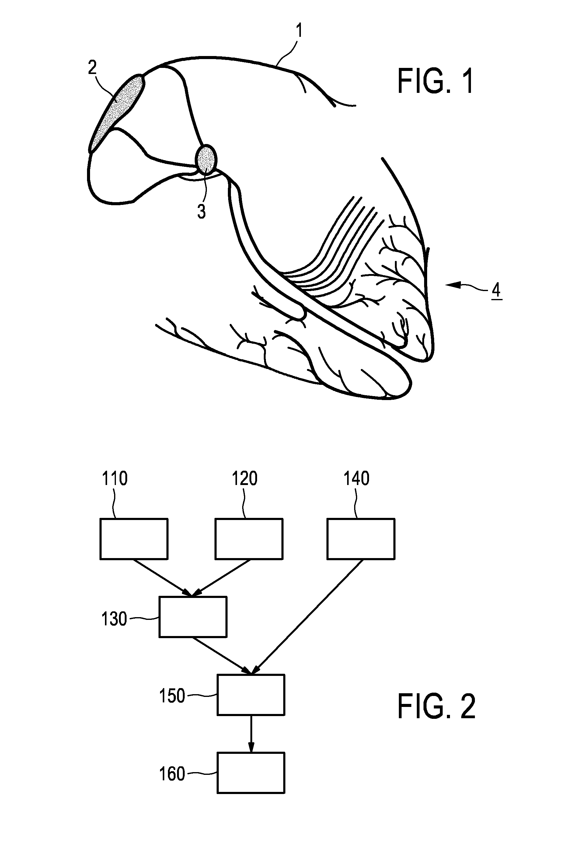
[0048]FIG. 1 shows a schematic representation of conduction tracts of a human heart, illustrating, amount others, the position of the Bachmann's bundle 1, the sinoatrial node 2, the atrioventricular node 3 and Purkinje fibers 4 as examples for conductions tracts.

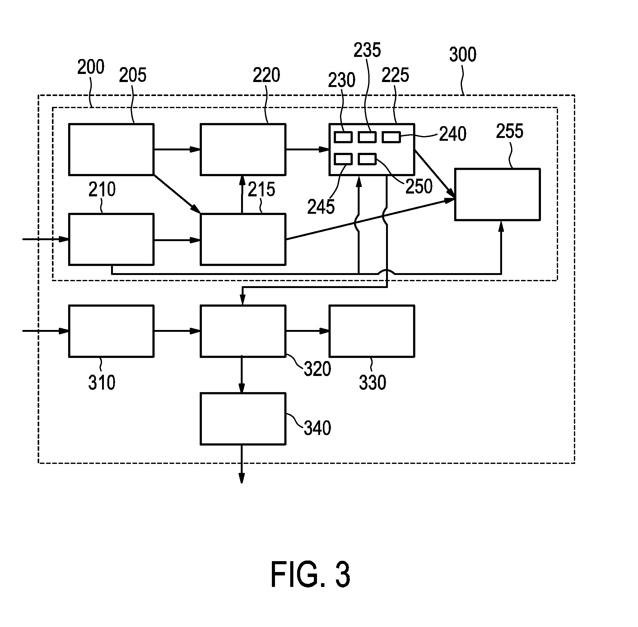
[0049]FIG. 2 shows a flow diagram illustrating an embodiment of a method for visualizing a conduction tract of a heart. In the exemplary embodiment, the shape (or at least characteristic landmarks that allow to reconstruct the shape) of the structures responsible for the electrophysiological conduction is encoded in the models of a cardiac segmentation framework (for details, see, for example, M. W. Krueger, F. M. Weber, G. Seemann, O. Dössel, “Semi-automatic segmentation of sinus node, Bachmann's Bundle and Terminal Crest for patient specific atrial models”, Proc. of World Congress on Medical Physics and Biomedical Engineering, IFMBE Proceedings, 25(4), 2010, 673-676).

[0050]The above is included in Step 110, in which theref...


PUM


Abstract

The invention relates to an apparatus, a method and a computer program for visualizing a conduction tract of a heart. In order to provide a visualization which is helpful in avoiding or finding the conduction tract in, for example, an invasive procedure like ablation of heart tissue, a generic heart model is adapted to geometrical data of the patient's heart, wherein model data indicating a shape and / or position of the conduction tract is modifying in accordance to the adaptation. The modification of the model data is further refined based on electrophysiological data and the refined model is used for generating a visualization.

Description

FIELD OF THE INVENTION[0001]The invention relates to an apparatus, a method and a computer program for visualizing a conduction tract of a heart.BACKGROUND OF THE INVENTION[0002]US 20110224962 A1 is related to an electrophysiological testing simulation for medical condition determination, wherein an aim is to identify scar tissue. This is done by thresholding, wherein scar tissue is identified due to different intensities. The eventual simulation is provided only for diagnosis purposes.[0003]US 20100191131 A1 is related to a method of noninvasive electrophysiological study of the heart, wherein activation maps are obtained of a surface heart model, which might be used by a medical practitioner to estimate where conduction tracts or structures might be located.[0004]In electrophysiological procedures, a scar in the heart tissue is created, for example, by ablation to interrupt an abnormal electrical conduction e.g. in case of atrial flutter. In the ablation procedure, it is important...

Claims


Application Information

Patent Timeline
Patent Type & Authority Applications(United States)
IPC IPC(8): A61B5/04A61B5/06A61B5/00A61B5/055A61B5/042A61B6/03
CPCA61B5/04011A61B5/061A61B5/743A61B5/055A61B6/032A61B5/042A61B5/6886A61B5/0402A61B2576/023G06T2210/41A61B5/7425A61B5/6852G06T17/00A61B5/283A61B5/367G16H30/40A61B5/0066A61B5/0084A61B8/44A61B8/445A61B5/318A61B5/341
Inventor GROTH, ALEXANDRAWEESE, JUERGENLEHMANN, HELKOBARSCHDORF, HANS
Owner KONINKLJIJKE PHILIPS NV
Learn More