
Microcatheter with Modified PTFE Liner

a micro-catheter and liner technology, applied in the field of aneurysms and blood clots, can solve problems such as difficult delivery, and achieve the effects of improving toughness, reducing friction coefficient, and improving delivery speed

Active Publication Date: 2015-01-22
TYCO HEALTHCARE GRP LP
View PDF12 Cites 45 Cited by
  • Summary
  • Abstract
  • Description
  • Claims
  • Application Information

AI Technical Summary

Benefits of technology

The patent describes a new microcatheter that makes it easier to deliver expandable devices for vascular reconstruction, like flow diversion tubes and embolization devices, into a patient's blood vessels. The microcatheter has a liner made of low friction and increased toughness, which reduces friction between the microcatheter and the devices and prevents any material from being deposited into the blood vessels. The liner is also only stretched longitudinally and not circumferentially or radially over at least a portion of the microcatheter's length. This results in reduced delivery friction, better toughness, and resistance to scraping. The microcatheter may also include additional layers or consist of a stretched PTFE liner without additional layers.

Problems solved by technology

The compressed shape exerts an outward radial force, which causes friction with the inner wall of the microcatheter and makes delivery difficult.

Method used


Image

  • Microcatheter with Modified PTFE Liner
  • Microcatheter with Modified PTFE Liner
  • Microcatheter with Modified PTFE Liner

Examples


Embodiment Construction

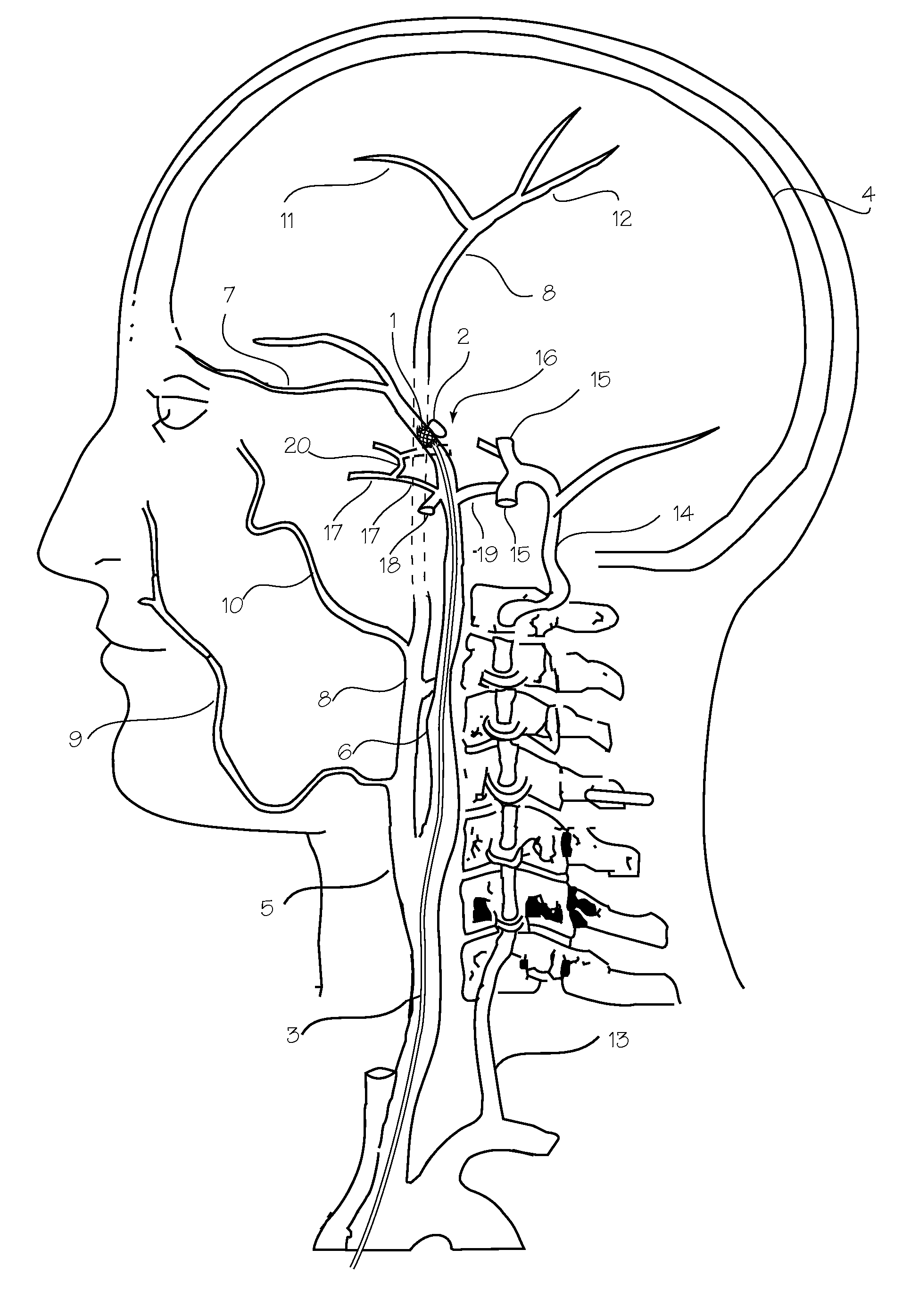
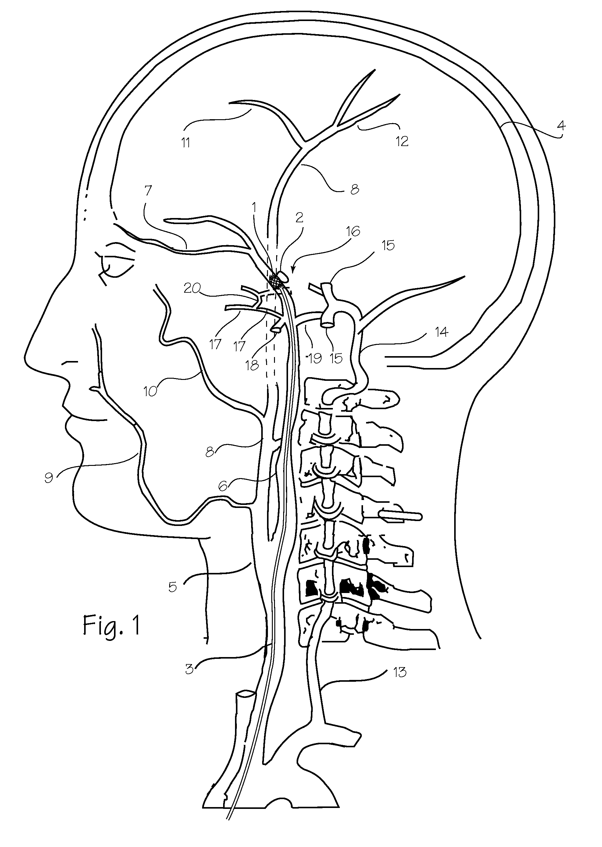
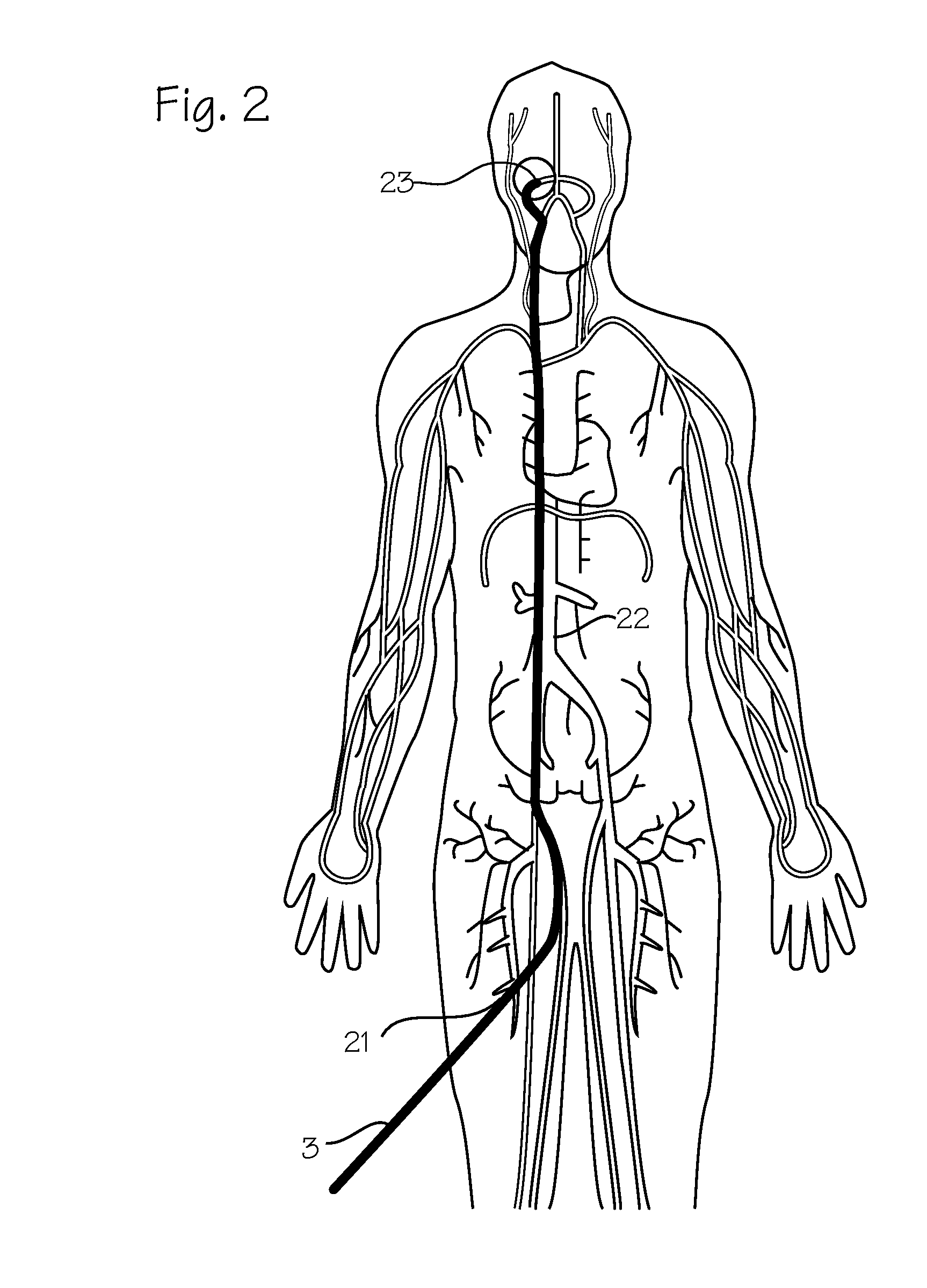
[0010]FIG. 1 is a schematic diagram of the vasculature of the brain showing placement of an expandable vascular reconstruction devices 1. The aneurysm treatment device is shown in an exemplary placement within the Circle of Willis. The aneurysm treatment device is delivered to this site of a vascular defect 2 via an enhanced microcatheter 3. The neuro-vasculature, which is the intended environment of use for the aneurysm treatment device, supplies the brain 4 with blood through the carotid and the vertebral arteries on each side of the neck. The important arteries the carotid artery 5 in the neck and the internal carotid artery 6 which supplies the ophthalmic artery 7. The external carotid 8 supplies the maxillary artery 9, the middle meningeal artery 10, and the superficial temporal arteries 11 (frontal) and 12 (parietal). The vertebral artery 13 supplies the basilar artery 14 and the cerebral arteries including the posterior cerebral artery 15 and the Circle of Willis indicated ge...


PUM

PropertyMeasurementUnit
Fractionaaaaaaaaaa
Fractionaaaaaaaaaa
Fractionaaaaaaaaaa

Abstract

A microcatheter with an enhanced inner liner that has low of friction and improved toughness which facilitates delivery of expandable vascular reconstruction devices.

Description

FIELD OF THE INVENTIONS[0001]The devices and methods described below relate to the field of treatments for aneurysms and blood clots.BACKGROUND OF THE INVENTIONS[0002]Intracranial aneurysms and clots can be treated with implantable devices such as flow diversion tubes, embolization devices, aneurysm bridging devices and scaffolding devices and thrombectomy devices. These devices are delivery through a microcatheter which is first delivered into an intracranial artery affected by an aneurysm or clot. Previously, these devices were preloaded onto the tips of microcatheters for introduction into a patient. More recent devices are not preloaded but are instead loaded via a proximal hub of the microcatheter, after the microcatheter has been placed with its distal tip deep in the intracranial vasculature, near the site of the aneurysm or blood clot. Examples of self-expanding devices delivered through microcatheters include neurovascular remodeling devices such as Covidien's Pipeline® emb...

Claims


Application Information

Patent Timeline
IPC IPC(8): A61B17/12A61M25/00
CPCA61B17/12113A61M25/0043A61M2025/0062A61M2025/0042A61M25/0009A61M25/0045A61M25/005A61M2025/0047A61F2/95A61B2017/1205
Inventor DINH, JAMES Q.VALKO, JEFFREY J.STRAUSS, BRIAN M.PERALTA, ADRIANA X.
Owner TYCO HEALTHCARE GRP LP
Learn More