System And Method For Monitoring Braking Effort

a technology of braking effort and system, applied in the direction of braking system, brake components, instruments, etc., can solve the problems of unsafe operation of vehicle systems, force applied, and degradation of braking systems

Active Publication Date: 2015-01-22
GE GLOBAL SOURCING LLC
View PDF2 Cites 22 Cited by
  • Summary
  • Abstract
  • Description
  • Claims
  • Application Information

AI Technical Summary

Benefits of technology

[0005]In an embodiment, a method (e.g., for monitoring a braking system of a vehicle system) includes monitoring fluid pressures of a braking system and modeled braking efforts of the braking system in a vehicle system traveling along a route, identifying one or more time periods at least one of before a brake event of the braking system or after the brake event, calculating residual forces exerted on the vehicle system during the one or more time periods, and determining at least one of an estimated braking effort of the braking system or an estimated propagation rate at which the estimated braking effort is applied by the braking system using the residual forces that are calculated. In one aspect, the time periods during which the residual forces are calculated include steady state time periods. During the steady state time periods, fluid pressure in the braking system and / or modeled braking efforts of the vehicle system do not change by more than one or more respective thresholds for at least a threshold time period.
[0006]In an embodiment, a control system (e.g., of a vehicle system) includes a vehicle controller configured to monitor fluid pressures of a braking system and modeled braking efforts of the braking system in a vehicle system traveling along a route. The vehicle controller also is configured to identify one or more time periods at least one of before a brake event of the braking system or after the brake event. The vehicle controller is further configured to calculate residual forces exerted on the vehicle system during the one or more time periods and determine at least one of an estimated braking effort of the braking system or an estimated propagation rate at which the estimated braking effort is applied by the braking system using the residual forces that are calculated. In one aspect, the time periods during which the residual forces are calculated include steady state time periods. During the steady state time periods, fluid pressure in the braking system and / or modeled braking efforts of the vehicle system do not change by more than one or more respective thresholds for at least a threshold time period.
[0007]In an embodiment, a method (e.g., for monitoring a braking system) includes measuring air pressures of an air braking system of a vehicle system before and after a brake event representing activation of the air braking system, modeling braking efforts provided by the air braking system before and after the brake event, identifying a pre-brake event time period when both the air pressures do not vary by more than a first threshold amount and the braking efforts that are modeled do not vary by more than a second threshold amount, calculating pre-brake event residual forces exerted on the vehicle system during the pre-brake event steady state time period, and estimating at least one of an actual braking effort of the air braking system or a propagation rate at which the actual braking effort is applied by the air braking system using the residual forces that are calculated.

Problems solved by technology

Due to inaccurate information used in calculating these forces and / or rates, degradation of the braking system, changes in the route being traveled, and other causes, the actual braking force that is applied may be less and / or the actual braking force may be supplied at a slower rate.
Because operators rely on the expected amounts of braking force that can be supplied and the rate at which the braking force is supplied to be accurate in order to safely operate the vehicle systems, inaccuracies in the braking force and / or rate can result in unsafe operation of the vehicle systems.

Method used


Image

  • System And Method For Monitoring Braking Effort
  • System And Method For Monitoring Braking Effort
  • System And Method For Monitoring Braking Effort

Examples


Embodiment Construction

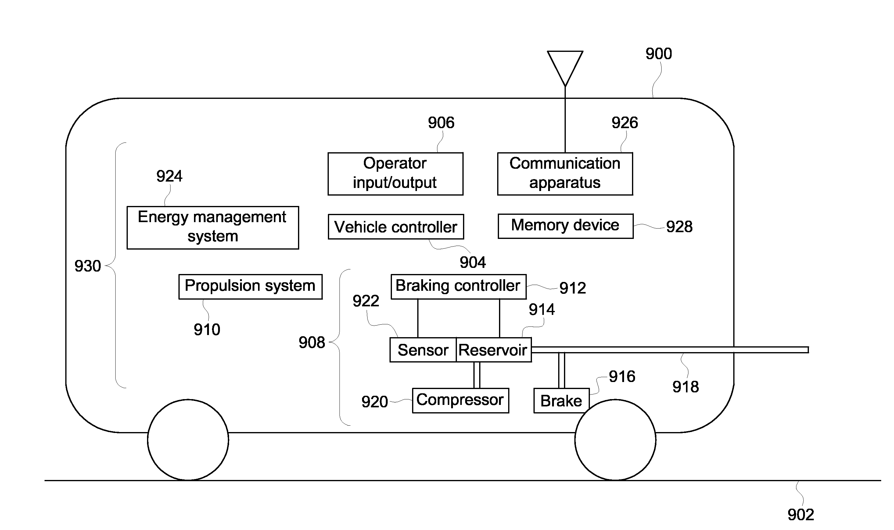
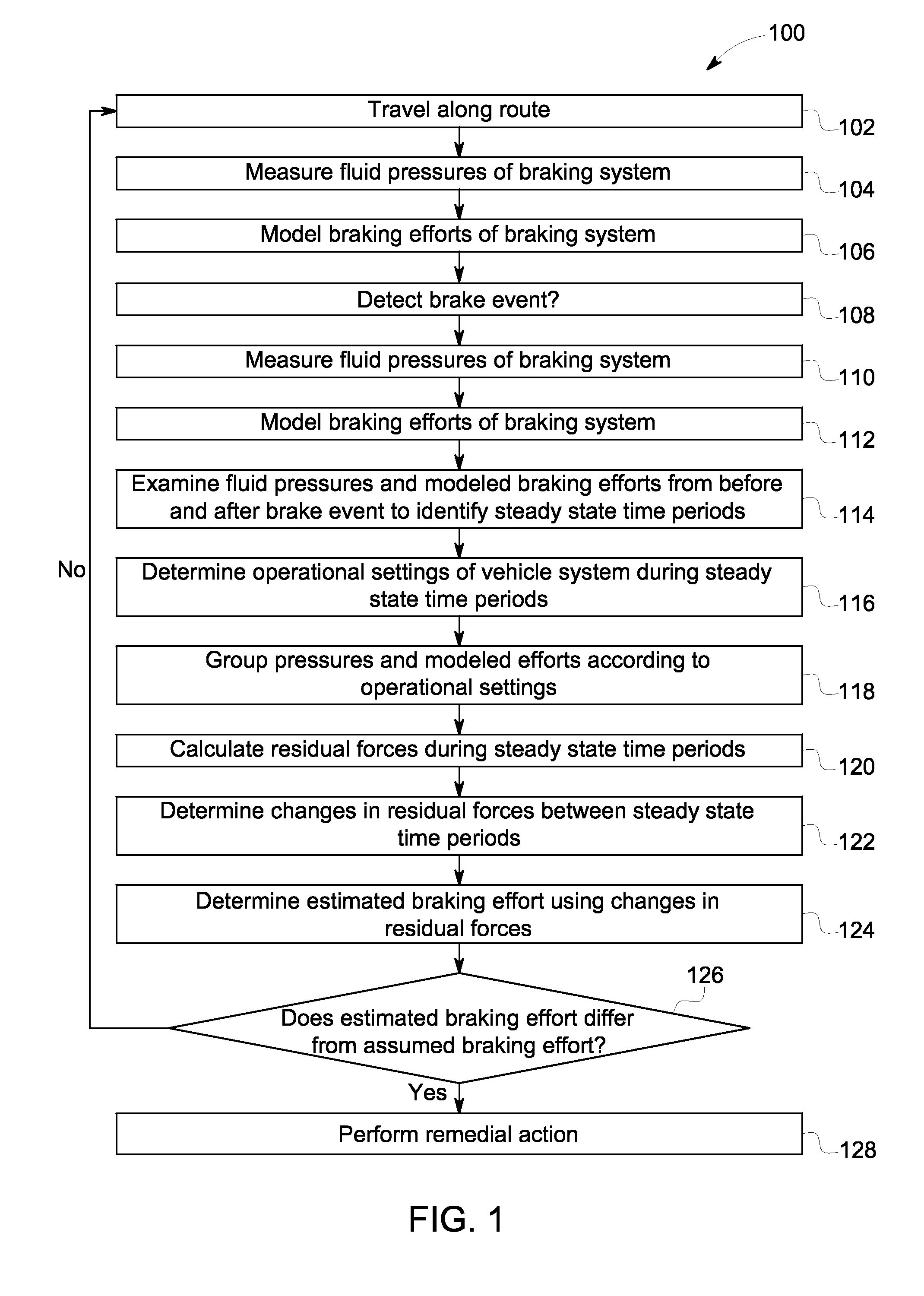
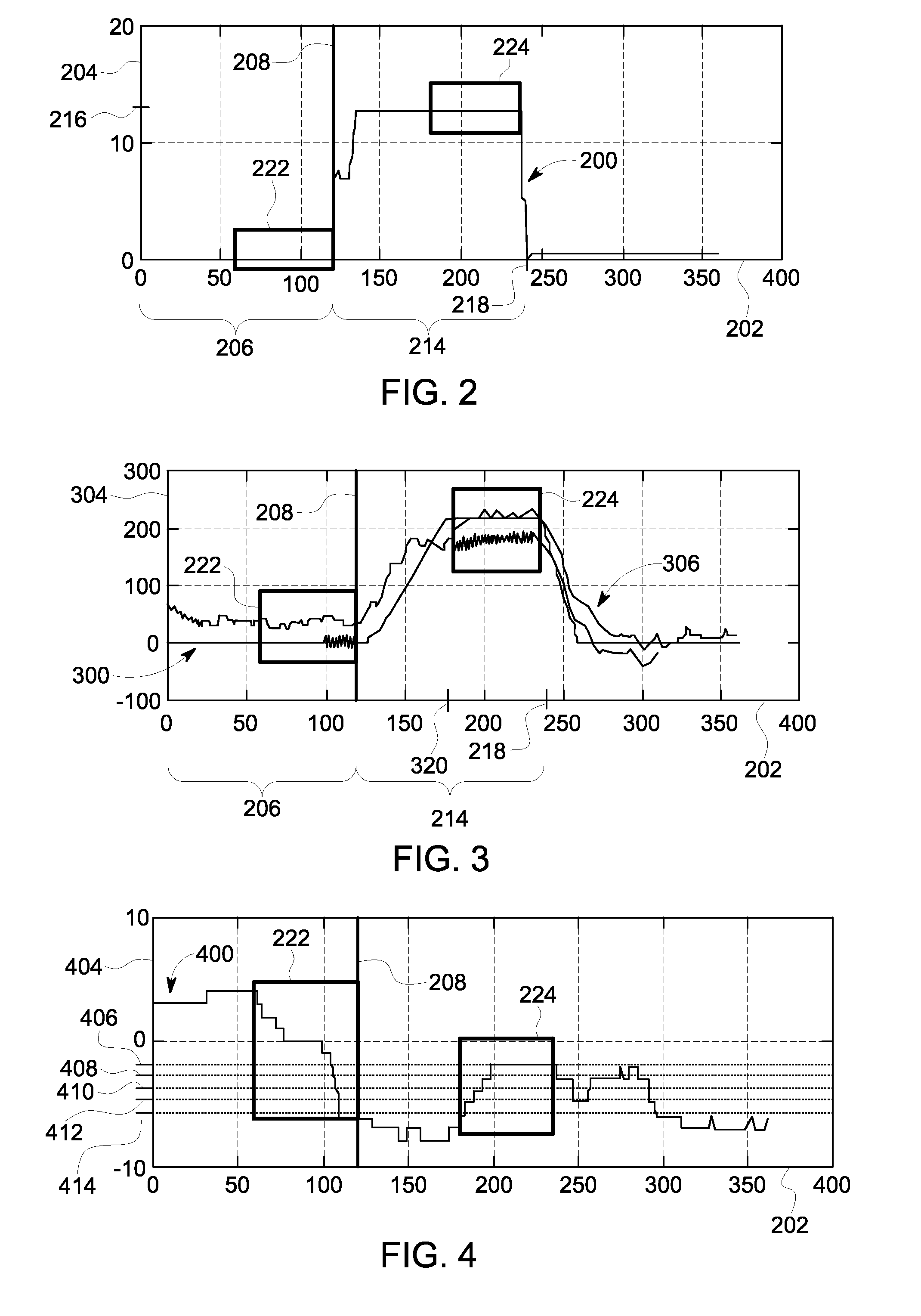
[0019]Embodiments of the inventive subject matter described herein relate to monitoring braking efforts generated by brakes of a vehicle system to stop or slow movement of the vehicle system. Braking efforts can include the resistive forces applied by brakes of the vehicle system that resist movement of the vehicle system. The braking efforts can be provided by air brakes of the vehicle system, such as a braking system that uses fluid pressure (e.g., air pressure) to keep the brakes disengaged and withhold the resistive forces but releases (e.g., reduces) the fluid pressure to engage the brakes and apply the resistive forces.

[0020]In one aspect, the fluid pressure of the braking system is monitored, such as by periodically or continuously measuring the fluid pressure held in a fluid reservoir onboard the vehicle system. Optionally, the fluid pressure can be measured in one or more conduits through which the fluid (e.g., air) is conveyed when the fluid pressure in the reservoir is re...


PUM


Abstract

A method (e.g., for monitoring a braking system of a vehicle system) includes monitoring fluid pressures of a braking system and modeled braking efforts of the braking system in a vehicle system traveling along a route, identifying one or more time periods at least one of before a brake event of the braking system or after the brake event, calculating residual forces exerted on the vehicle system during the one or more time periods, and determining at least one of an estimated braking effort of the braking system or an estimated propagation rate at which the estimated braking effort is applied by the braking system using the residual forces that are calculated.

Description

FIELD[0001]Embodiments of the subject matter described herein relate to monitoring braking effort (e.g., braking forces) applied by brakes of a vehicle system.BACKGROUND[0002]Some known vehicle systems include braking systems that rely on air pressure to control the braking system. (As used herein, the term “vehicle system” may refer to a single vehicle or multiple vehicles mechanically coupled with each other, such as in a vehicle consist. A vehicle may include a propulsion-generating vehicle capable of self-propulsion or a non-propulsion-generating vehicle that is incapable of self-propulsion.) For example, air brakes are prevented from engaging moving parts of the vehicle systems by maintaining sufficient air pressure in conduits of the braking system that includes the air brakes. In order to activate the air brakes, the pressure is decreased so that the braking system no longer is prevented from engaging the moving components of the vehicle system. The braking system engages the...

Claims


Application Information

Patent Timeline
Patent Type & Authority Applications(United States)
IPC IPC(8): B60T17/22
CPCB60T17/22B60T17/221
Inventor HERMSEN, BRYAN SCOTTKUMAR, AJITH KUTTANNAIRMATTHEWS, JR., HARRY KIRKDOWN, JOHN HARRYMEYER, BRIAN NEDWARD
Owner GE GLOBAL SOURCING LLC
Why Eureka
Try Eureka