Image sensor unit and image reading device

a technology of image sensor and reading device, which is applied in the direction of instruments, lenses, radio frequency control devices, etc., can solve the problems of reducing the image reading performance, affecting the reading or outputting of images by cis, and affecting the reading of images, etc., to achieve accurate and easy positioning, stable, and excellent output image

Inactive Publication Date: 2015-01-29
NISCA KK
View PDF2 Cites 5 Cited by
  • Summary
  • Abstract
  • Description
  • Claims
  • Application Information

AI Technical Summary

Benefits of technology

[0021]In this manner, the rod lens array is disposed with respect to the light receiving sensor. As a result, a narrow space is established as being closed by the extension portions of the substrates of the rod lens array, in such a way that the photoelectric conversion elements are enclosed between an emission surface of the rod lens array and the sensor substrate. Therefore, even if the operating distance of the rod lenses becomes longer, it is possible to prevent, in an effective manner, dust from getting into an optical path between the rod lenses and the photoelectric conversion elements, or from adhering to emission surfaces of the rod lenses or light receiving surfaces of the photoelectric conversion elements. Furthermore, the rod lens array can be positioned accurately and easily at a desired height and planar position with respect to the sensor substrate.
[0022]In an example, the rod lens array is engaged with the sensor substrate as lower ends of the extension portions of the substrates come in contact with an upper surface of the sensor substrate or as the lower ends of the extension portions of the substrates are fitted into holes provided on the upper surface of the sensor substrate. Therefore, the rod lens array can be easily disposed at a desired position with respect to the light receiving sensor.
[0023]Moreover, according to the present invention, provided is an image reading device that includes the above image sensor unit of the present invention. Therefore, a stable, excellent output image can be obtained at any time.

Problems solved by technology

The CIS could have an adverse effect on the reading of images or outputting of sensors if dust gets into the CIS from the outside or if processing debris comes off from components inside the CIS.
However, if the radius r0 of the lens is made smaller, the handling and processing of the rod lens becomes difficult when the rod lens is produced.
As a result, there might be a decrease in the image reading performance.
Therefore, the rod lens array and the image sensor that includes the rod lens array cannot be made smaller in size.
The possibility is relatively low that the reading of images and the outputting of sensors are adversely affected as dust gets into the space from the outside or as processing debris or the like comes off from components inside the space.
Such a large space allows dust to easily get in, and the dust inside the space can easily move and enter the optical path between the rod lens array and the light receiving sensor or adhere to the emission surface of the rod lens or the photoelectric conversion elements of the light receiving sensor, possibly causing an adverse effect on the reading of images and the outputting of sensors.
However, the CIS disclosed in Jpn. Pat. Appln. Laid-Open Publication No. 05-344276 does not pay attention at all to the effect of dust getting into the space between the rod lens array and the light receiving sensor (For example, see paragraph 0028 of the document).
Therefore, it is difficult to ensure stable performance.

Method used


Image

  • Image sensor unit and image reading device
  • Image sensor unit and image reading device
  • Image sensor unit and image reading device

Examples


Embodiment Construction

[0034]Hereinafter, a preferred embodiment of the present invention will be described in detail with reference to the accompanying drawings.

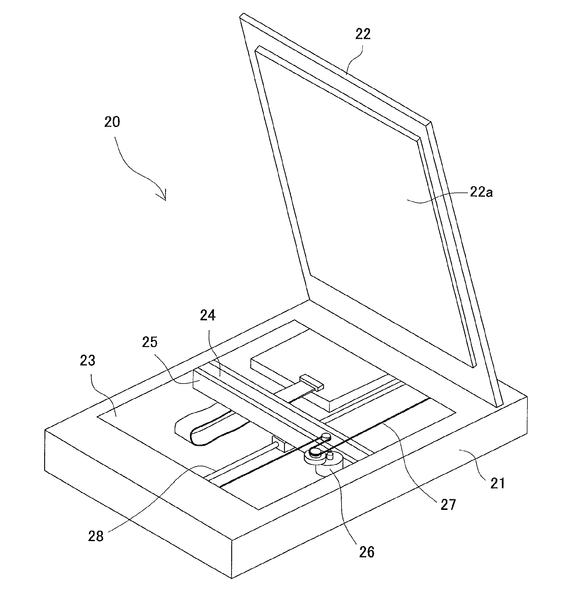
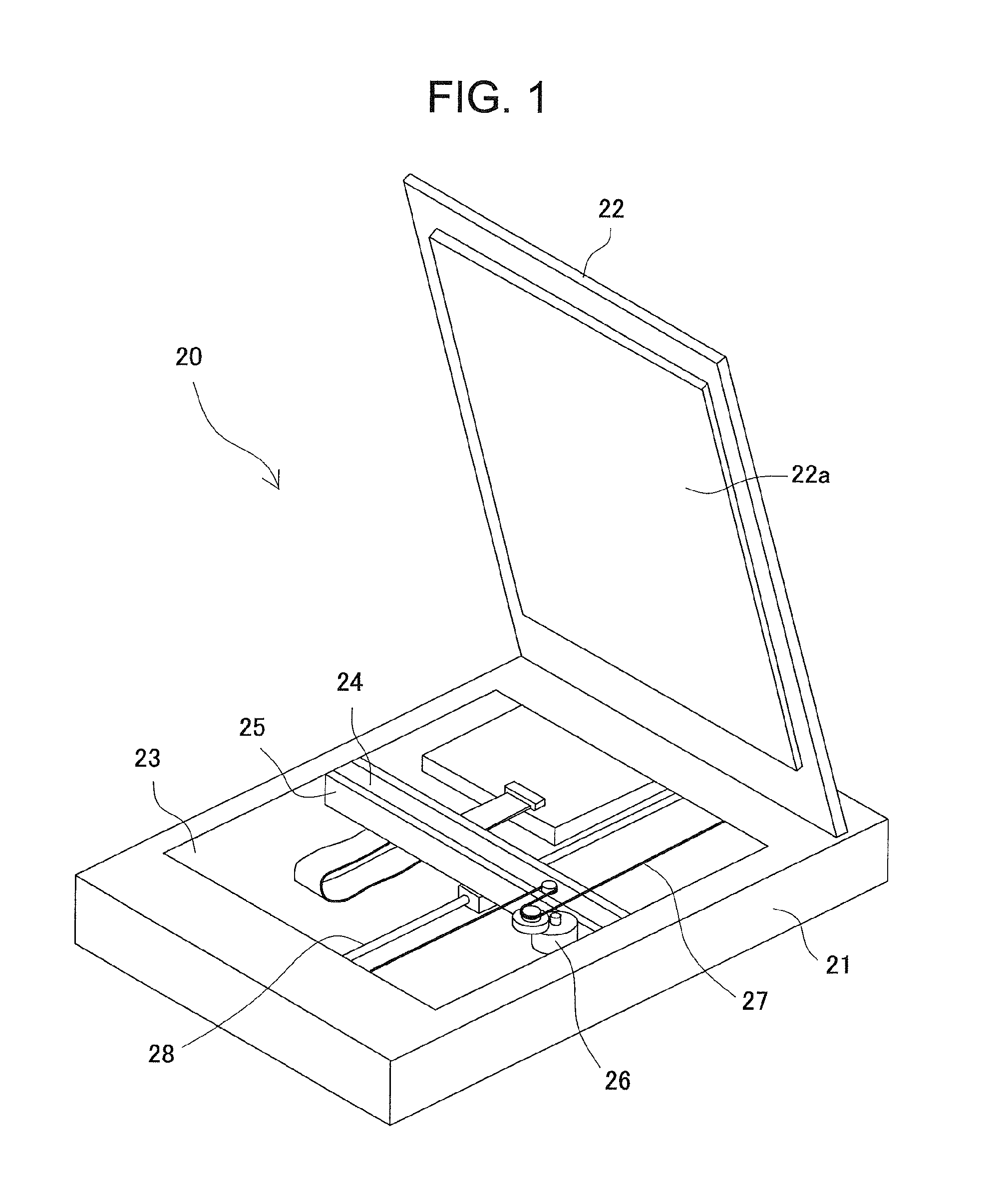
[0035]FIG. 1 is a schematic perspective view of an image scanner on which an image sensor unit of a preferred embodiment of the present invention is mounted. An image scanner 20 of the present embodiment is an image reading device of a flatbed type. The image scanner 20 includes a main body 21, which is substantially in the shape of a rectangular box, and a platen cover 22, one end of which is mounted on the main body through a hinge (not shown) in such a way that the platen cover 22 can be freely opened or closed.

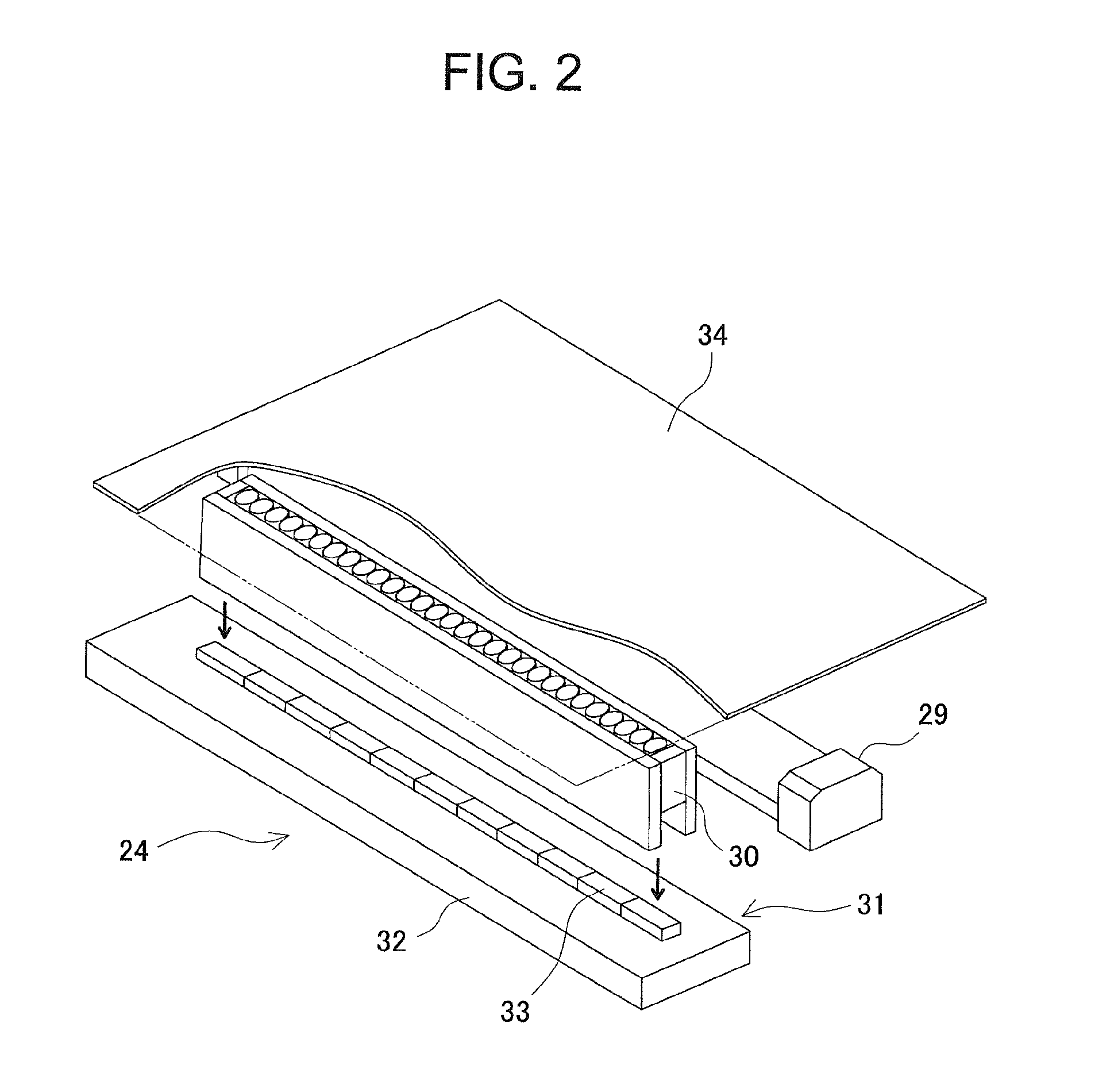
[0036]The may body 21 includes a platen glass 23, which is a large rectangular transparent glass plate fixed on an upper surface thereof, and a contact-type image sensor unit 24 of the present invention. On an upper surface of the platen glass 23, a to-be-read document is placed with a document surface thereof down. When the platen cove...


PUM


Abstract

A contact-type image sensor is designed to prevent, in an effective manner, dust from entering into a space between a rod lens array and a light receiving sensor. A rod lens array includes a large number of rod lenses between two flat substrates and between spacers located at left and right ends; one row of the rod lenses is arranged in such a way that central axes of the rod lenses become parallel to each other. At an emission side of a rod lens in an axis line direction, each substrate includes an extension portion, whose length is determined based on an operating distance of the rod lens. A lower end of the extension portion of each substrate is in contact with an upper surface of a sensor substrate. In this manner, the rod lens array is positioned with high accuracy with respect to the light receiving sensor.

Description

BACKGROUND OF THE INVENTION[0001]1. Technical Field[0002]The present invention relates to an image sensor unit that is used in image reading devices, such as image scanners, or other various optical devices, and to an image reading device that includes the image sensor unit.[0003]2. Description of Related Art[0004]In conventional image reading devices, such as facsimile machines, copiers, image scanners, or printers, and other various optical devices, a contact-type image sensor (CIS) of an equal-magnification image-forming optical system is widely used to optically read an image on a document and convert the image into electric signals. The CIS includes a rod lens array in which one or more rows of many cylindrical rod lenses are arranged between two substrates in such a way that the central axes of the lenses become parallel to each other (For example, see Jpn. Pat. Appln. Laid-Open Publication No. 2012-244344).[0005]The rod lens is so designed as to have a refractive index distri...

Claims


Application Information

Patent Timeline
Patent Type & Authority Applications(United States)
IPC IPC(8): H04N1/00H01L27/146
CPCH04N1/00909H01L27/14625H04N1/00557G02B3/0087G02B13/0095G02B27/0075G02B27/123
Inventor KAGAMI, YUICHIOGINO, KOUJI
Owner NISCA KK
Why Eureka
Try Eureka