
High speed tester communication interface between test slice and trays

Active Publication Date: 2015-01-29
ADVANTEST CORP
View PDF12 Cites 46 Cited by
  • Summary
  • Abstract
  • Description
  • Claims
  • Application Information

AI Technical Summary

Benefits of technology

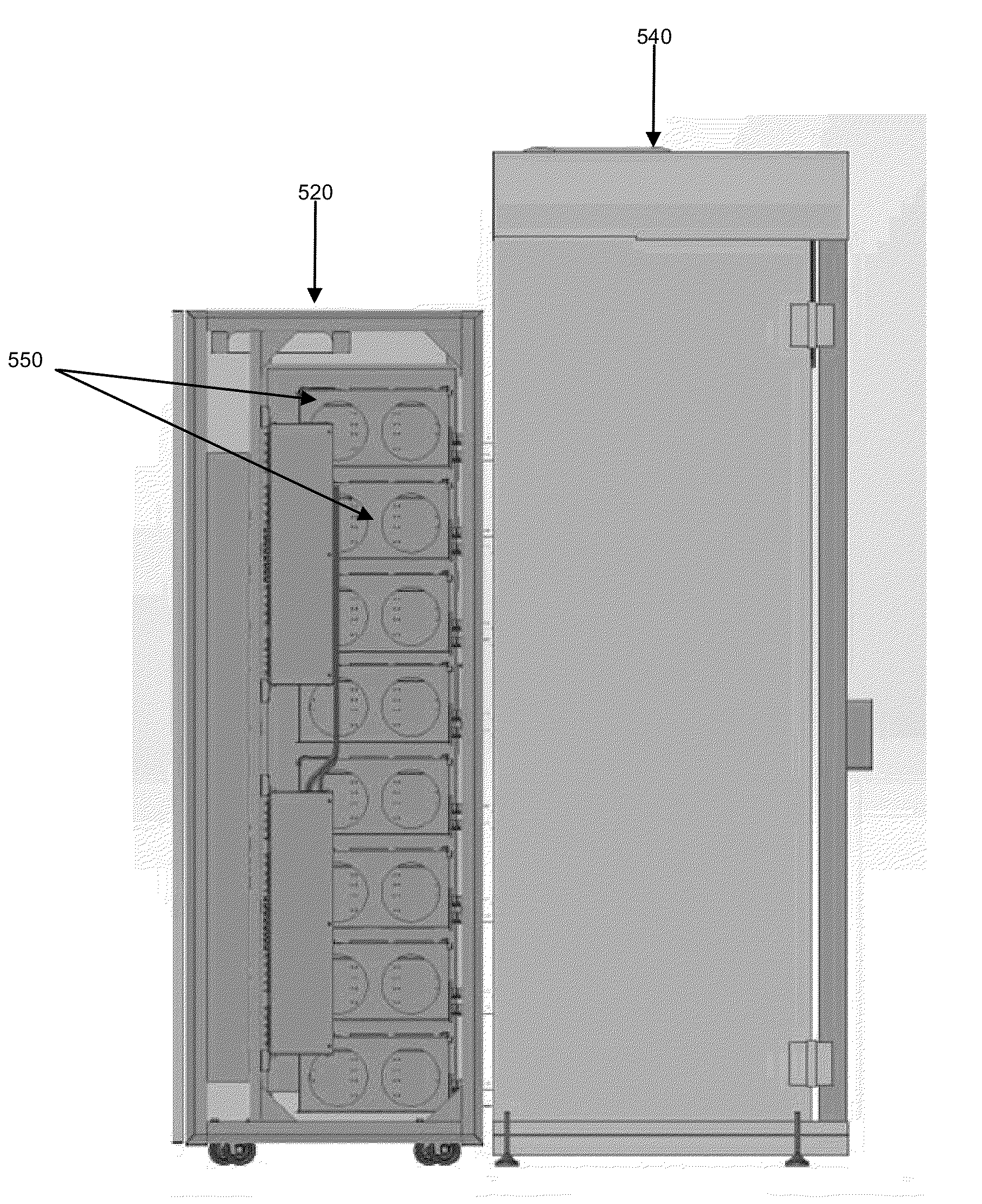
The patent text is discussing the need for a tester architecture that can address issues with current systems. The proposed test architecture is designed to provide a high-speed means for testing devices through an oven wall and allows for optimal space utilization by horizontal stacking of devices. Additionally, it enables hot swapping and hot plugging of devices.

Problems solved by technology

Additionally, reliability problems can be dealt with by component “burn-in” which includes testing the DUTs at increased temperature to induce infant mortality failures at the factory.
One of the challenges associated with burn-in is interconnecting the components of the system, e.g., controls, power supplies, etc. with the DUTs while they are in the thermal chamber.
Typically, in conventional systems, it is challenging to perform high speed testing of the DUTs because the signals experience losses in signal integrity as they travel to the DUTs.
This is because the methods usually used to connect the DUTs to the controls can be lossy over long distances.
Accordingly, conventional thermal chambers only support low speed testing of DUTs.
Further, in conventional systems, it is challenging to stack DUTs horizontally far from the oven wall because long traces on printed circuit boards (PCBs) needed to reach all the DUTs result in issues with signal integrity within the system.
As a result, the space within the thermal chamber could not typically be optimized.
This can prolong oven down-time and reduce testing throughput.

Method used


Image

  • High speed tester communication interface between test slice and trays
  • High speed tester communication interface between test slice and trays
  • High speed tester communication interface between test slice and trays

Examples


Embodiment Construction

[0033]Reference will now be made in detail to the various embodiments of the present disclosure, examples of which are illustrated in the accompanying drawings. While described in conjunction with these embodiments, it will be understood that they are not intended to limit the disclosure to these embodiments. On the contrary, the disclosure is intended to cover alternatives, modifications and equivalents, which may be included within the spirit and scope of the disclosure as defined by the appended claims. Furthermore, in the following detailed description of the present disclosure, numerous specific details are set forth in order to provide a thorough understanding of the present disclosure. However, it will be understood that the present disclosure may be practiced without these specific details. In other instances, well-known methods, procedures, components, and circuits have not been described in detail so as not to unnecessarily obscure aspects of the present disclosure.

[0034]S...


PUM


Abstract

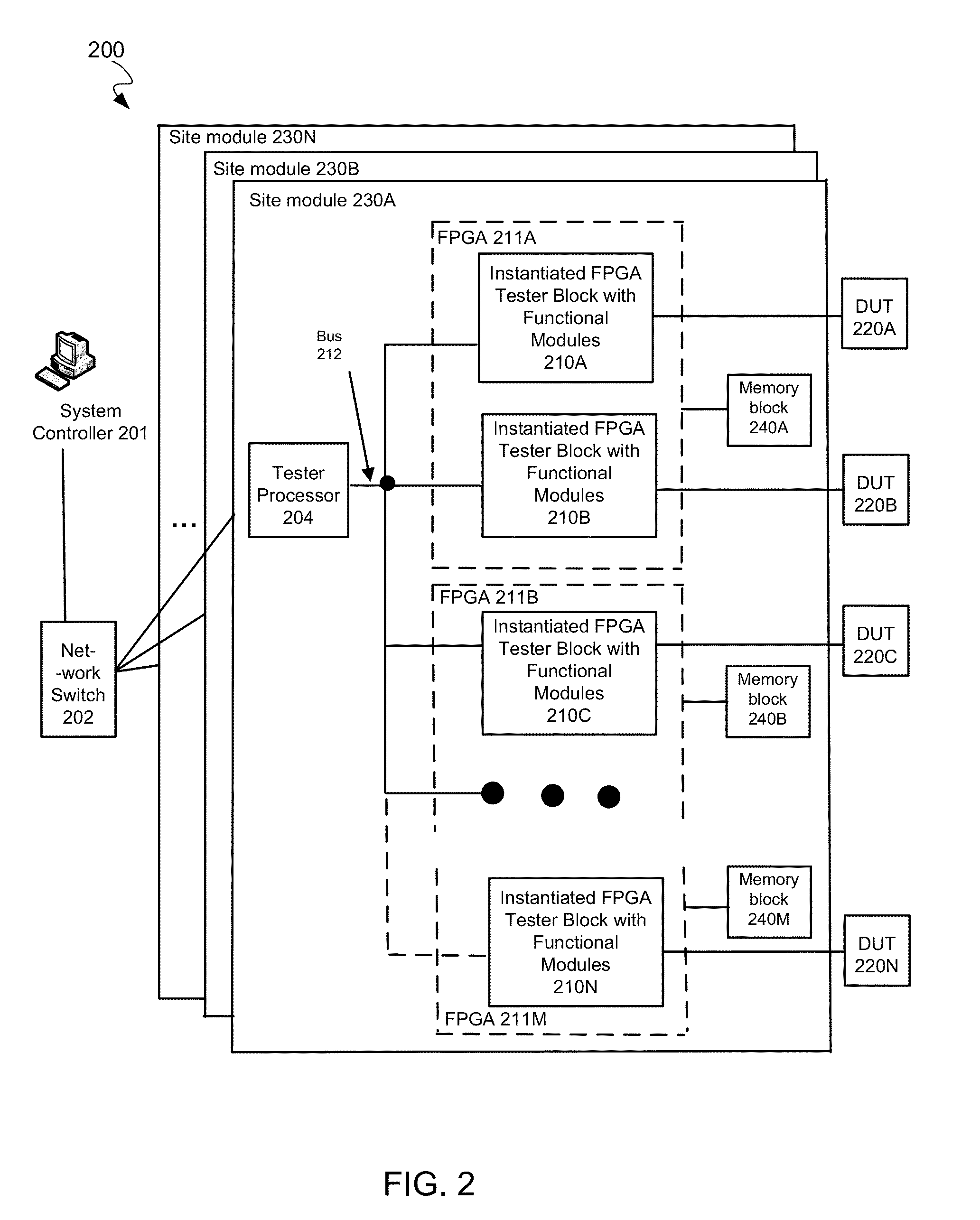
A tester system is disclosed. The tester system comprises a tester module operable to generate test signals for testing a plurality of DUTs. It also comprises a plurality of cables operable to communicatively couple the tester module with a tray comprising the plurality of DUTs through a thermal chamber wall interface. Further, it comprises a plurality of connectors in contact with the tray, wherein the plurality of connectors is operable to provide an interface between the plurality of cables and conductive traces on the tray, and further wherein each of the plurality of connectors is operable to pass a respective subset of the test signals to each DUT on the tray via the conductive traces.

Description

CROSS-REFERENCE TO RELATED APPLICATIONSRelated Applications[0001]The present application is related to U.S. patent application Ser. No. 13 / 773,580, filed Feb. 21, 2013, entitled “A TESTER WITH MIXED PROTOCOL ENGINE IN A FPGA BLOCK,” naming John Frediani and Andrew Niemic as inventors, and having attorney docket number ATST-JP0089. That application is incorporated herein by reference in its entirety and for all purposes.[0002]The present application is related to U.S. patent application Ser. No. 13 / 773,555, filed Feb. 21, 2013, entitled “A TESTER WITH ACCELERATION ON MEMORY AND ACCELERATION FOR AUTOMATIC PATTERN GENERATION WITHIN A FPGA BLOCK,” naming John Frediani as inventor, and having attorney docket number ATST-JP0091. That application is incorporated herein by reference in its entirety and for all purposes.[0003]The present application is related to U.S. patent application Ser. No. 13 / 733,569 filed Feb. 21, 2013, entitled “A TEST ARCHITECTURE HAVING MULTIPLE FPGA BASED HARDWARE...

Claims


Application Information

Patent Timeline
IPC IPC(8): G01R31/26G01R31/00
CPCG01R31/003G01R31/2601G01R31/2863G06F11/2221G11C29/56012G11C2029/5602G01R31/2889
Inventor KUSHNICK, ERICSU, MEI-MEIWOLFF, ROLAND
Owner ADVANTEST CORP
Learn More