Sensor-containing connection element and manufacturing method

a technology of connection element and manufacturing method, which is applied in the direction of screws, instruments, force/torque/work measurement apparatus, etc., can solve the problems of low cost, affecting the quality of the connection, etc., and achieves the effect of low cos

Active Publication Date: 2015-01-29
GLBS PATENTVERWERTUNGSGESELLSCHAFT GBR
View PDF18 Cites 17 Cited by
  • Summary
  • Abstract
  • Description
  • Claims
  • Application Information

AI Technical Summary

Benefits of technology

[0034]The teaching according to the invention is also intended to serve for producing the support structure at low cost. A small constructional space requirement for the sensor technology and the pretensioning thereof is to be required.

Problems solved by technology

This may change, however, due to operating loads, temperature fluctuations or settling effects.
This is, however, costly for commercially available screw means after completing the tightening process.
Maintenance cycles at chronologically fixed intervals also have the drawback that the connections could fail during the cycles.
Generally, a differential construction which has as a feature the cumulative combination of individual parts with potentially different materials is disadvantageous with regard to the complexity during manufacture and the resulting costs.
From a technological perspective, the teaching based on a differential construction often has drawbacks due to the many individual parts in the flux of force and the resulting resilience and spreading due to the production tolerances of the individual components.
This invention has the drawback that further elements have to be built into the connection which produce additional resilience, require particular measures and costs during the mounting procedure and the complexity of the construction is high.
When this teaching is used, the construction has proved to be unsatisfactory as elements have to be positioned relative to one another which is costly.
However, the measuring structure is very complex and thus not cost-effective.
Additionally, the device is purely limited to the measurement of the pretensioning.
In this case, the continuous monitoring proves problematic and impossible for optically implemented systems.
This proposed solution does not appear to be suitable for the purpose of continuous and automatic evaluation.
This teaching has the drawback that a further element has to be built into the connection which causes additional resilience, requires particular measures and costs during the mounting procedure and increases the complexity of the construction.
After the tightening procedure said devices are removed again and, as a result, are no longer available for measurements on the connection element.
Said arrangement, however, does not remain permanently installed on the screw connection and also requires an operator.
Drawbacks here are the complexity of the construction and the size of the device, whereby the potential uses are limited.
This invention has the drawback that further elements have to be built into the connection which cause an additional resilience, require particular measures and costs during the mounting procedure and increase the complexity of the construction.
A drawback in these inventions is that the capacitive sensor is not installed in the screw itself which may give a false reading of the measurement.
This invention has the drawback that a further element has to be built into the connection which causes additional resilience, requires specific measures and costs during the mounting procedure and increases the complexity of the construction.
The sensitive layers on the surface are disadvantageous here.
These layers may be easily damaged during the mounting procedure or during operation which leads to a false reading of the measurement values.
A drawback is the susceptibility to interference from the surroundings.
The sensitive layers on the surface are disadvantageous here.
Said layers may be easily damaged during the mounting procedure or during operation which leads to a false reading of the measurement values.
Due to the many individual parts and shaped elements required, however, it is a costly construction.
The cost when applying this teaching appears to be excessively high for fastening purposes.
Also DE 10 2006 007 385 A1 detects shear forces occurring in a bolt by means of strain gauges and thus does not satisfy any connection purpose.
The load-bearing capacity of this connection element is, however, reduced by its type of construction as it is slotted over extensive areas.
A drawback is the complex construction which is demanded by the geometric elements required.

Method used


Image

  • Sensor-containing connection element and manufacturing method
  • Sensor-containing connection element and manufacturing method
  • Sensor-containing connection element and manufacturing method

Examples


Embodiment Construction

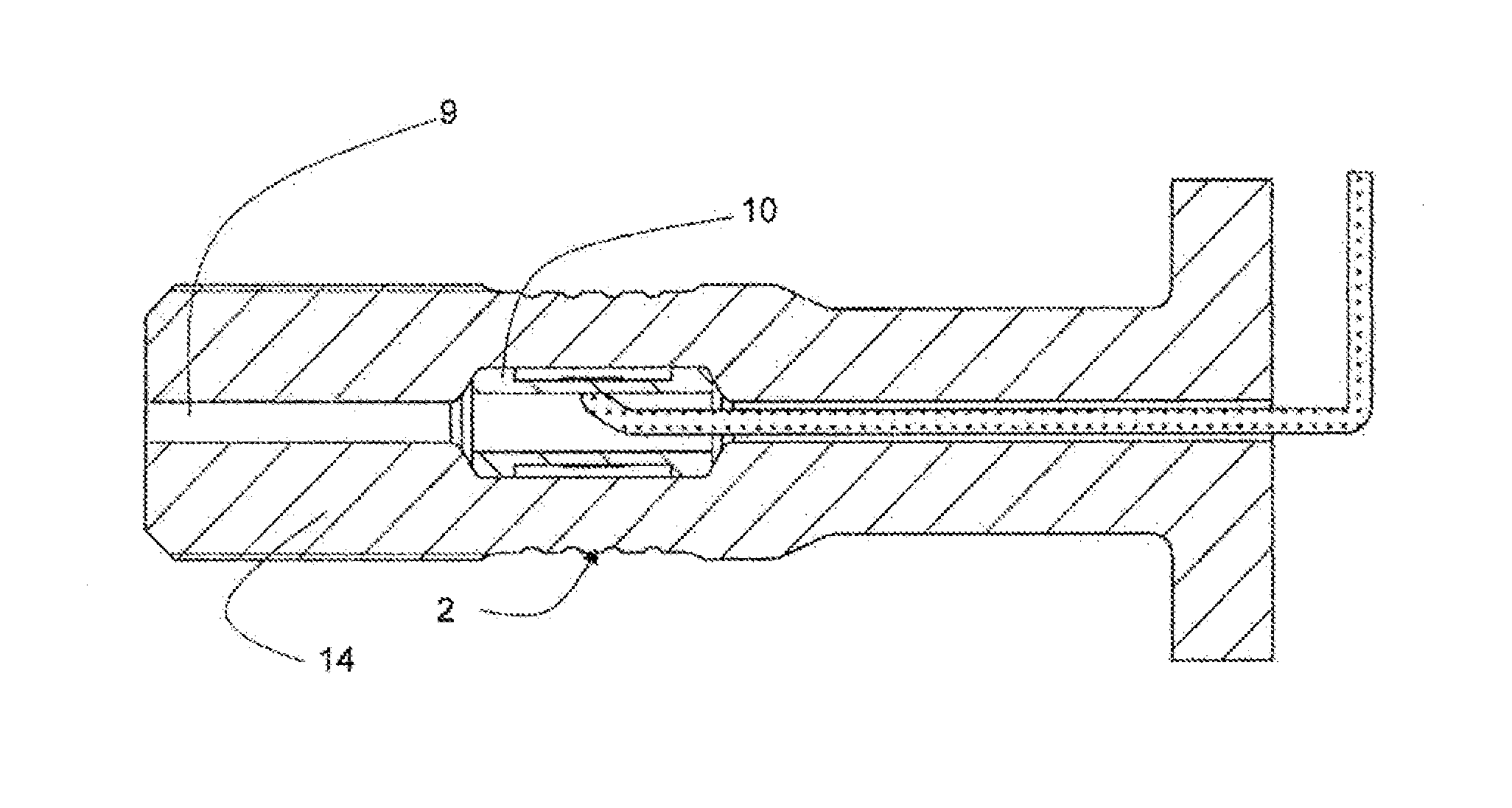
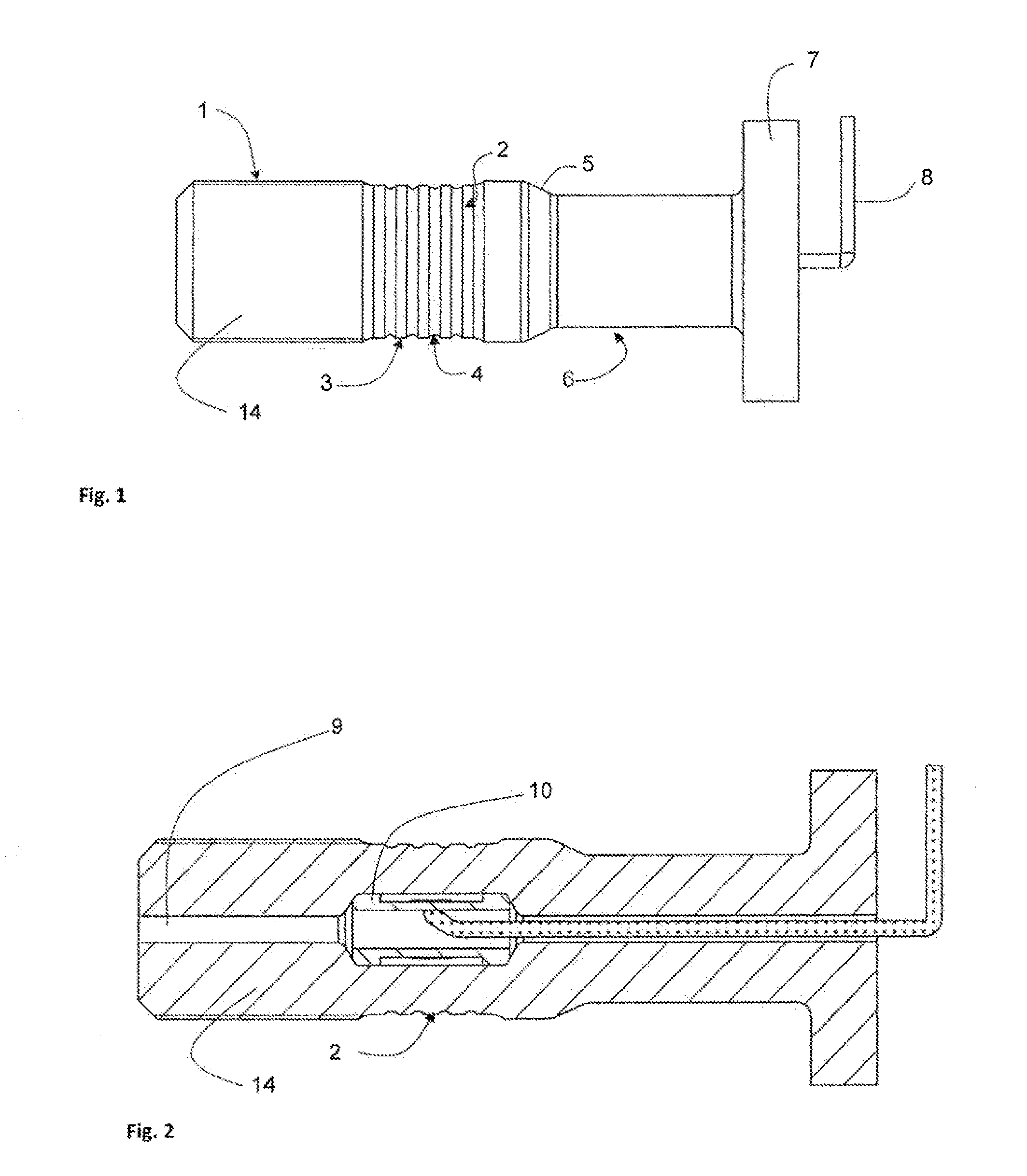
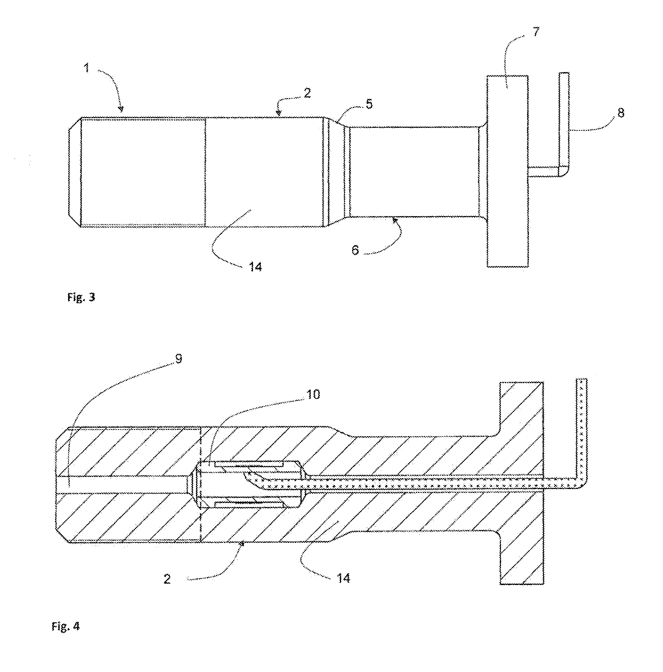
[0050]According to the invention, the proposed construction substantially consists of a longitudinally oriented support structure (14) and a sensor unit (10). The object of the support structure (14) is that of a connection element. The support structure (14) consists of a threaded region (1) at the ends thereof, as well as a top part (7), or alternatively, a further threaded region (1) or a further top part (7). A resilient region (2) inside which the sensor unit (10) is integrated is provided in addition. The sensor unit (10) in this case is located in the secondary flux of force of the support structure (14) and is arranged coaxially in the interior thereof. In order to exploit further the advantages of this simple construction, the sensor unit (10) is intended to be integrated during the manufacturing process of the support structure (14). The sensor unit (10) undertakes the task of measuring the axial pretensioning force acting in the connection element as well as transverse fo...


PUM

PropertyMeasurementUnit
plastic deformationaaaaaaaaaa
forcesaaaaaaaaaa
signal transmissionaaaaaaaaaa

Abstract

A connection element consists of a longitudinally oriented support structure that is at least partially hollow and a sensor unit that is arranged in the inside of the support structure, is connected to a signal transmission device, and is non-positively connected to the support structure. The required force for the non-positive connection is produced by internal stresses after a plastic deformation of the support structure during a joining process of the support structure and the sensor unit. A method for manufacturing a connection element consisting of a support structure that is at least partially hollow and a sensor unit includes positioning the sensor unit in a region of the support structure and, using radially movable tool segments, exerting a force on the support structure in the radial direction and at the same time reducing the periphery of the support structure in the region in which the sensor unit is positioned.

Description

CROSS REFERENCE TO RELATED APPLICATIONS[0001]This United States national stage patent application claims the benefit of priority to International (PCT) Application No. PCT / EP2013 / 000824 filed on Mar. 19, 2013, which in turn claims the benefit of priority to German Patent Application No. DE 10 2012 005 614.1, filed on Mar. 22, 2012, the entire disclosures of which are incorporated herein by reference.FIELD OF THE INVENTION[0002]The invention relates to a support structure performing the task of a connection element with integrated sensor technology for detecting loads as well as the effective direction thereof with an interface for outputting measurement variables suitable for automated signal processing. The connection element may be, for example, a screw, a bolt, a threaded rod, a rivet or an anchoring bolt. The invention further relates to the manufacture of this arrangement by plastic shaping.BACKGROUND OF THE INVENTION AND RELATED ART[0003]In many areas of the prior art, for exa...

Claims


Application Information

Patent Timeline
Patent Type & Authority Applications(United States)
IPC IPC(8): F16B31/02B21K25/00B23P11/02
CPCF16B31/02B21K25/00B23P11/025B21K1/44F16B31/025G01L5/24G01L5/0004Y10T29/49865Y10T29/49925G01D11/30G01L5/00
Inventor GROCHE, PETERBRENNEIS, MATTHIAS
Owner GLBS PATENTVERWERTUNGSGESELLSCHAFT GBR
Why Eureka
Try Eureka