Dental implant, abutment, implant system and implant set

a technology of dental implants and abutments, applied in dentistry, dental surgery, medical science, etc., can solve the problems of relatively slow increase of implant wall thickness, inability to achieve deep transmission of pushing force, and low self-inhibition, so as to achieve maximum functional sealing against contamination, high reliability and durability, the effect of high self-inhibition

Active Publication Date: 2015-01-29
SIC INVENT
View PDF23 Cites 9 Cited by
  • Summary
  • Abstract
  • Description
  • Claims
  • Application Information

AI Technical Summary

Benefits of technology

[0041]The advantages of the invention are in particular that as a result of a connection of a Morse taper with an adjoining indexing section and the resulting possibility of the deep introduction of forces acting on the abutment, an implant and an implant system can be created with high reliability and durability.
[0042]As a result of the configuration of the taper section as Morse taper a high self inhibition by friction fit and the tendency for cold welding is realized. As a result a form fitting and force fitting connection between the abutment and the implant is generated. Due to the cold welding a maximal functional sealing against contamination is also realized. In particular in the case of an implant interface, which is anchored in the implant over a length of 4 mm, only a minimal widening and bulging of the contact surface should occur even under dynamic load. With this a maximal tightness against entering fluids and bacteria is ensured.
[0043]Due to the reduced elastic deformation resulting from the inner geometry and with this reduced loads acting on the bone, the tendency to bone degradation is reduced.
[0044]The parallel-walled side surfaces of the grooves provided for securement against rotation and oriented at 0° relative to introduced torques, realize a particularly advantageous shape in which no push frictions are generated, which would for example be generated by an oblique force introduction in a hexagon. Thus there is no tendency that the high torques during screwing in the implant involving high surface pressures on the transmission surfaces, lead to cold welding of the retention surfaces. This means that a desired cold welding can be achieved in a targeted manner in the taper part while at the same time an undesired cold welding in the indexing part can be avoided.
[0045]As a result of a circular support surface adjoining the taper, the abutment can be supported during introduction without jamming in an intermediate position. The treating dental technician or the physician can locate the index of the interface by rotating the abutment in any direction. Thereby the abutment softly and quasi automatically glides with the cams into the inner contour of the implant interface.

Problems solved by technology

The deep transmission of pushing forces cannot be achieved with a rather shallow taper because due the predetermined outer diameter of the implant, the shallow taper does not reach far enough into the implant in vertical direction.
The steep angle further leads to an even and relatively slow increase of the implant wall thickness.

Method used


Image

  • Dental implant, abutment, implant system and implant set
  • Dental implant, abutment, implant system and implant set
  • Dental implant, abutment, implant system and implant set

Examples


Embodiment Construction

[0074]Throughout all the Figures, same or corresponding elements are generally indicated by same reference numerals. These depicted embodiments are to be understood as illustrative of the invention and not as limiting in any way. It should also be understood that the drawings are not necessarily to scale and that the embodiments are sometimes illustrated by graphic symbols, phantom lines, diagrammatic representations and fragmentary views. In certain instances, details which are not necessary for an understanding of the present invention or which render other details difficult to perceive may have been omitted.

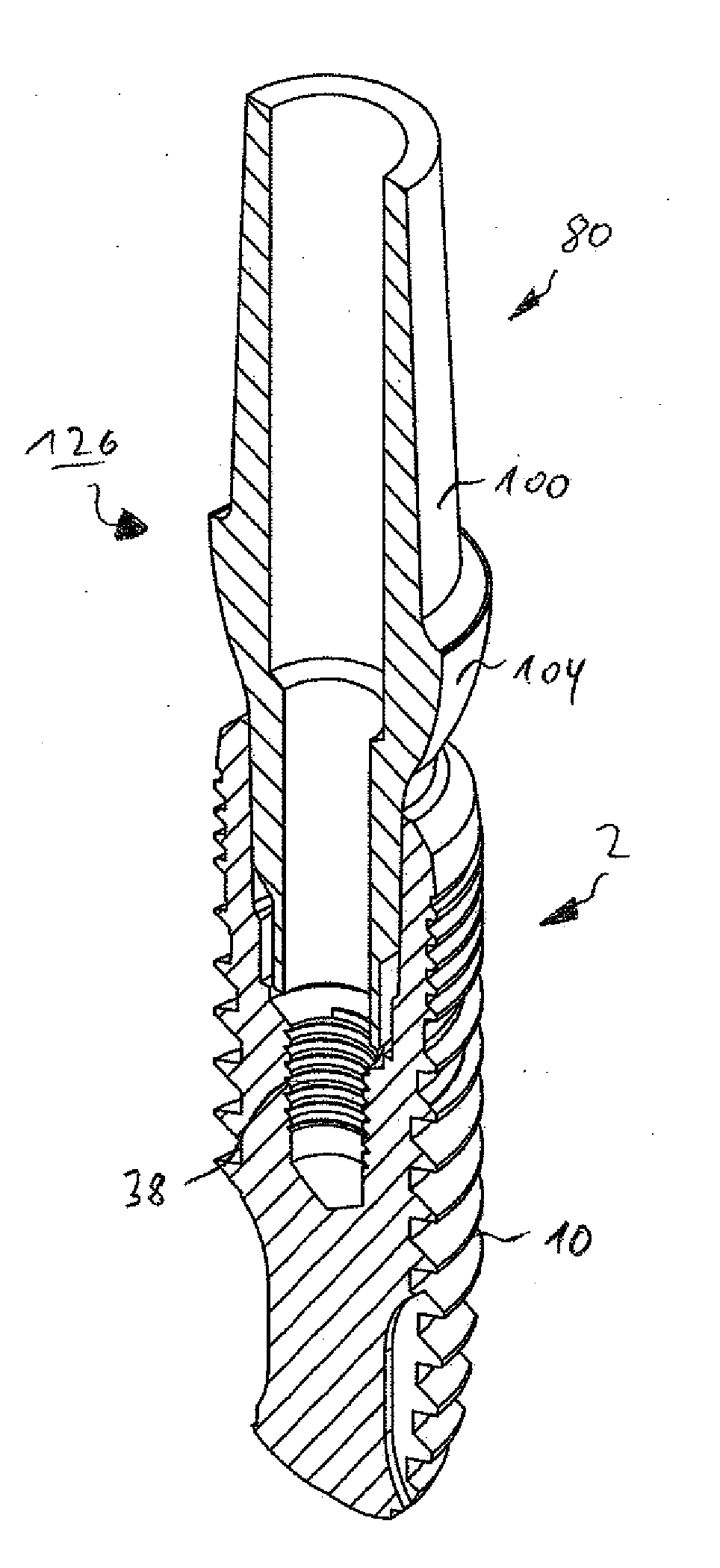
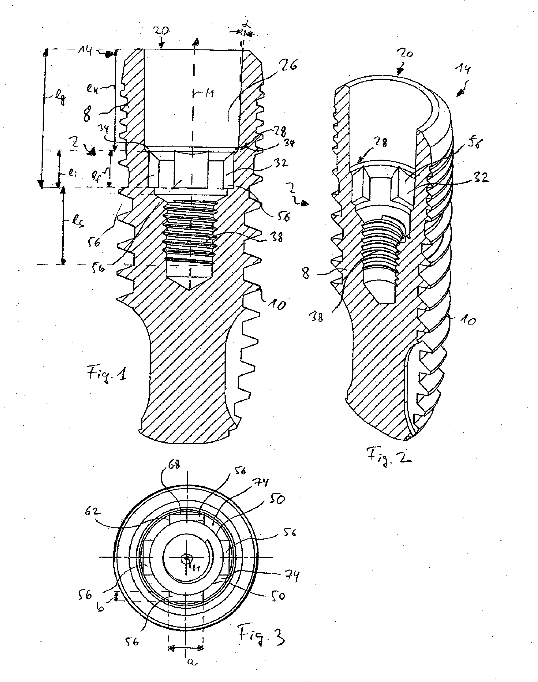
[0075]A dental implant 2 shown in a side section in FIG. 1 and in a perspective section in FIG. 1, has an implant body 8, which is made substantially from pure titanium Grade 4 and an outer threading 10. Other preferred materials are for example titanium Grade 5 or titanium alloys.

[0076]At a coronal end 14 the dental implant 2 has a receiving opening 20 for receiving an abutme...


PUM


Abstract

A dental implant for insertion in a jaw bone has a receiving opening arranged on a coronal end of the dental implant for an abutment, the receiving opening when viewed from the coronal end having a taper section and an indexing section, the indexing section having at least one outwardly extending groove arranged along a circular circumference, the taper section having a conical angle of less than 3°.

Description

CROSS-REFERENCES TO RELATED APPLICATIONS[0001]This application claims the priority of European Patent Application, Serial No. EP13178279, filed Jul. 27, 2013, pursuant to 35 U.S.C. 119(a)-(d), the disclosure of which is incorporated herein by reference.BACKGROUND OF THE INVENTION[0002]The present invention relates to a dental implant, an abutment, an implant system and an implant set.[0003]The following discussion of related art is provided to assist the reader in understanding the advantages of the invention, and is not to be construed as an admission that this related art is prior art to this invention.[0004]The treatment of a patient with artificial dental prostheses, which replace the previously present natural teeth, usually has esthetic as well as medical reasons. On one hand the impression of a complete set of teeth can be created. On the other hand the absence of teeth can also lead to physical changes in the bone structure in the region of the jaw, displacements or “migrati...

Claims


Application Information

Patent Timeline
Patent Type & Authority Applications(United States)
IPC IPC(8): A61C8/00
CPCA61C8/0066A61C8/0069A61C8/0068A61C8/0022A61C8/0071A61C8/0001A61C8/008
Inventor VON MALOTTKI, MARCUSSCHILLI, WILFRIED
Owner SIC INVENT
Why Eureka
Try Eureka