
Cutting apparatus for cutting food items conveyed on a conveyor including at least one conveyor belt

a technology of conveyor belts and cutting equipment, which is applied in the direction of feeding apparatus, meat shaping/cutting, automatic control devices, etc., can solve the problems of inability to achieve x-ray imaging, reducing costs, and reducing the cost of using such belts, so as to improve the efficiency and precision of the cutting apparatus, mitigate, alleviate or eliminate one

Inactive Publication Date: 2015-02-05
MAREL ICELAND EHF
View PDF13 Cites 25 Cited by
  • Summary
  • Abstract
  • Description
  • Claims
  • Application Information

AI Technical Summary

Benefits of technology

The patent text describes a food processing system that uses a single conveyor for both x-ray imaging and cutting. This eliminates errors in displacement and cutting due to transferring between conveyors. The cutting can occur on a thin solid belt, which is easier to clean and has lower costs compared to stainless steel conveyors. The system also allows for real-time monitoring of the cutting process. The technical effects of this system include improved accuracy in trimming and compact design.

Problems solved by technology

Also, the costs relating to using such belts is typically much lower compared to such cutting belts.
Further, similar type of belt may be implemented for this cutting apparatus as in the remaining conveyors in the food processing system which results in e.g. lowers costs.
Additionally, the food items may be imaged at all times, e.g. shortly before the cutting starts and also during the cutting, but such an imaging, e.g. x-ray imaging, is not possible on a such cutting belts.

Method used


Image

  • Cutting apparatus for cutting food items conveyed on a conveyor including at least one conveyor belt
  • Cutting apparatus for cutting food items conveyed on a conveyor including at least one conveyor belt
  • Cutting apparatus for cutting food items conveyed on a conveyor including at least one conveyor belt

Examples


Embodiment Construction

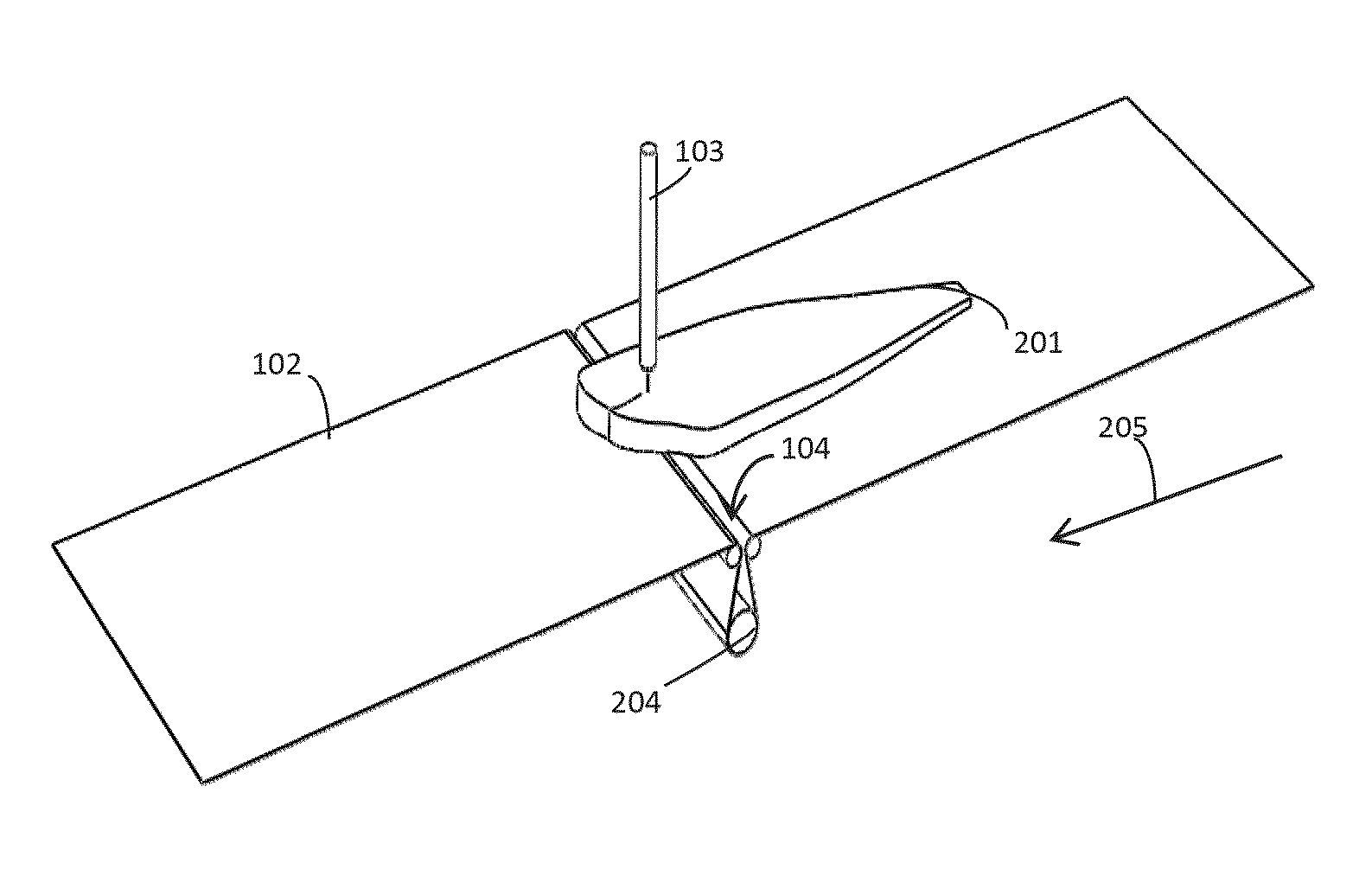
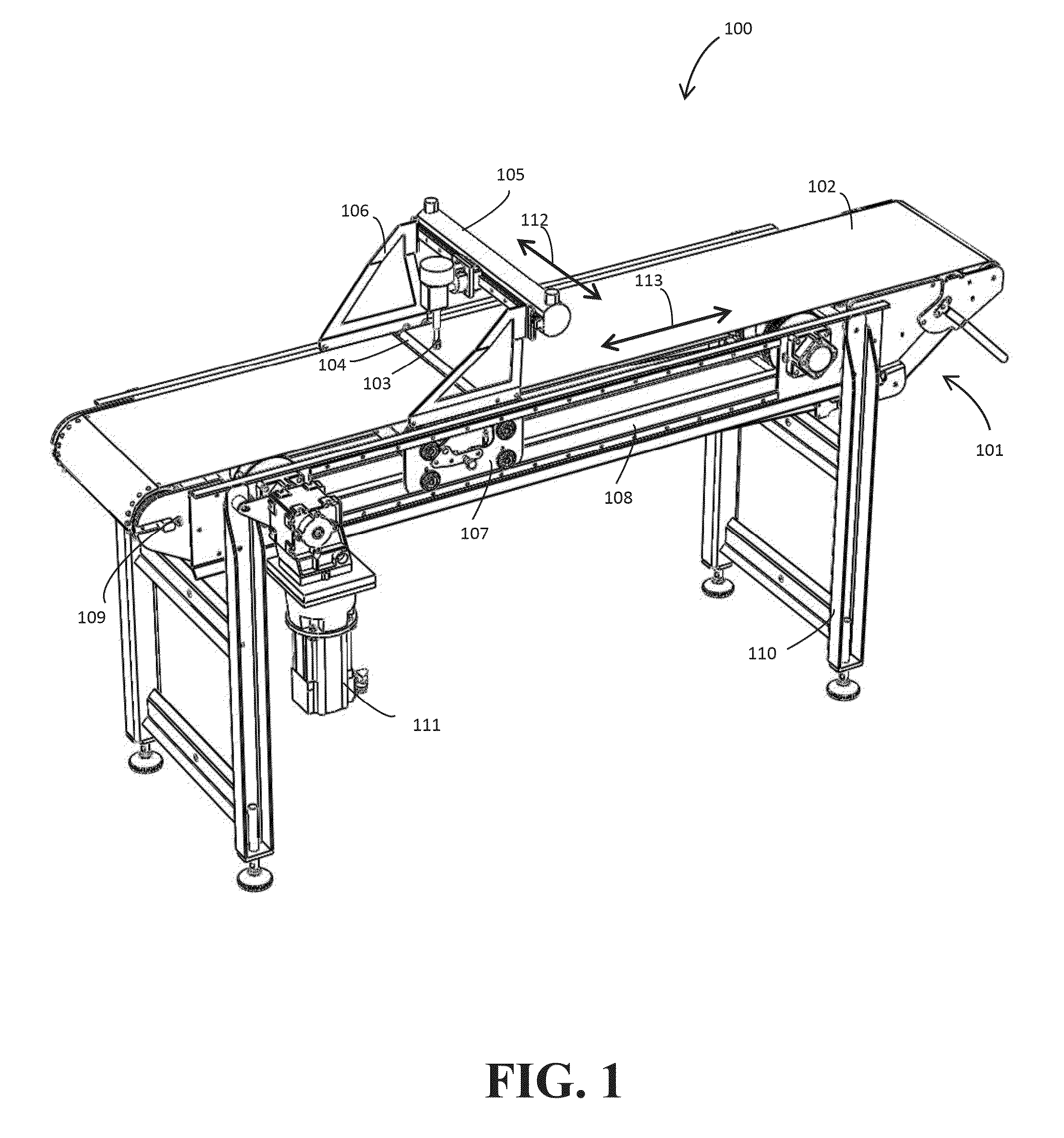
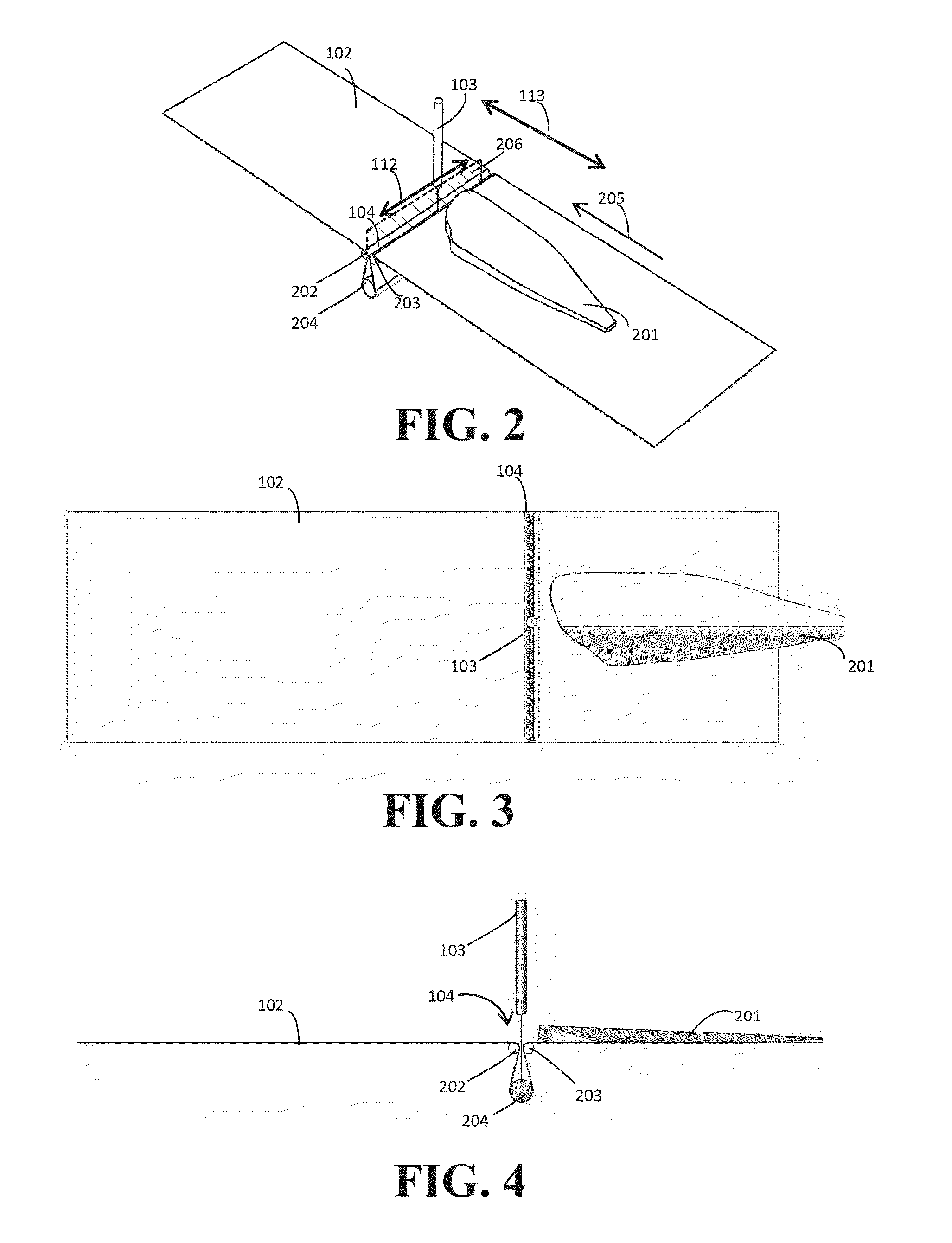
[0071]FIG. 1 shows a perspective view of an embodiment of a cutting apparatus 100 according to the present invention for cutting food items conveyed on a conveyor 101 including a conveyor belt 102. The apparatus comprises a cutter 103 that is arranged above a gap 104 extending across the conveyor belt 102. The gap is formed between adjacent elongated supporting means such as adjacent rollers with a fixed internal arrangement. This will be discussed in more details in relation to the remaining figures. The conveyor belt 102 may be made of any type of deflecting material that may be of solid type such as any type of rubber or plastic material and / or any type of belt that is stiff in the transversal direction and flexible in the longitudinal direction such as an Intralox belt type.

[0072]The cutter may be, but is not limited to, a fluid pressure cutter, a laser beam cutter, a high pressurized gas cutter, or a cutting blade, where the cutter is slideable mounted to a track 105 positioned...


PUM

PropertyMeasurementUnit
acute anglesaaaaaaaaaa
acute angleaaaaaaaaaa
tensionaaaaaaaaaa

Abstract

This invention relates to a cutting apparatus for cutting food items conveyed on a conveyor including at least one conveyor belt. A cutter is arranged above a gap extending across the at least one conveyor belt. The cutter is positioned in relation to the gap such that the cutting path of the cutter extends through the food items and the gap and below the surface level of the at least one conveyor belt. The cutter is adapted to be connected to a control mechanism for operating crosswise movement of the cutter along the gap. The gap is formed between adjacent elongated supporting means such as rollers with a fixed internal arrangement, where the adjacent elongated supporting means and the cutter is adapted to be connected to a control mechanism for operating back and forth movement of the adjacent elongated supporting means and the cutter parallel to the conveying direction while maintaining the internal arrangement of the adjacent elongated supporting means and the cutter fixed.

Description

FIELD OF THE INVENTION[0001]The present invention relates to a cutting apparatus for cutting food items conveyed on a conveyor including at least one conveyor belt and further to a food processing system comprising such cutting apparatus.BACKGROUND OF THE INVENTION[0002]Undesired objects such as tissues or bones in food items such as fish fillets, poultry fillets and meat may be removed in an automatic way via cutting, where the cutting is performed in accordance to images taken of the food items that identify the locations of the tissues / bones to be cut and removed. Today, the food items are often moved or placed on a first conveyor that may include a thin solid belt where the imaging, e.g. x-ray imaging, takes place while the food items are being conveyed. Since the cutting involves implementing cutting procedure such as high pressure water jet that extends below the surface of the conveyor belt the objects must me moved onto a special cutting belt, typically a stainless steel con...

Claims


Application Information

Patent Timeline
Patent Type & Authority Applications(United States)
IPC IPC(8): B26D5/34B65G15/28B26D1/04B26F3/00B26D7/06B26D5/00A22C17/00B26D7/18
CPCB26D5/34A22C17/0006A22C17/0086A22C17/0093B26D1/04B26D7/18B26F3/004B26D7/0625B26D5/007B65G15/28A22C17/002B65G15/00Y10T83/364Y10T83/4691Y10T83/242Y10T83/145
Inventor FINNSSON, THORIR
Owner MAREL ICELAND EHF
Learn More