Roll-off piston for an air spring rolling-lobe flexible member

a flexible member and air spring technology, applied in the field of rolling-off pistons, can solve the problems of material brittleness, material is relatively hard and brittle, can splinter, etc., and achieves the effect of reducing production costs, reducing production costs, and improving service li

a flexible member and air spring technology, applied in the field of rolling-off pistons, can solve the problems of material brittleness, material is relatively hard and brittle, can splinter, etc., and achieves the effect of reducing production costs, reducing production costs, and improving service li

US20150035213A1Active Publication Date: 2015-02-05CONTITECH LUFTFEDERSYST

Image

  • Roll-off piston for an air spring rolling-lobe flexible member
  • Roll-off piston for an air spring rolling-lobe flexible member
  • Roll-off piston for an air spring rolling-lobe flexible member

Examples


Embodiment Construction

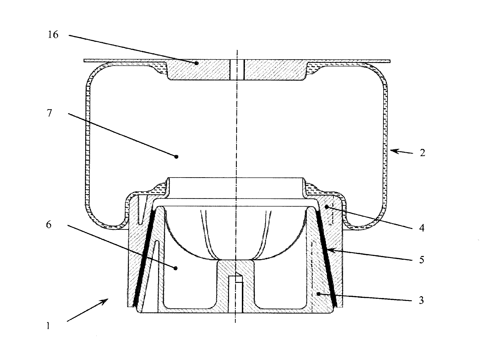
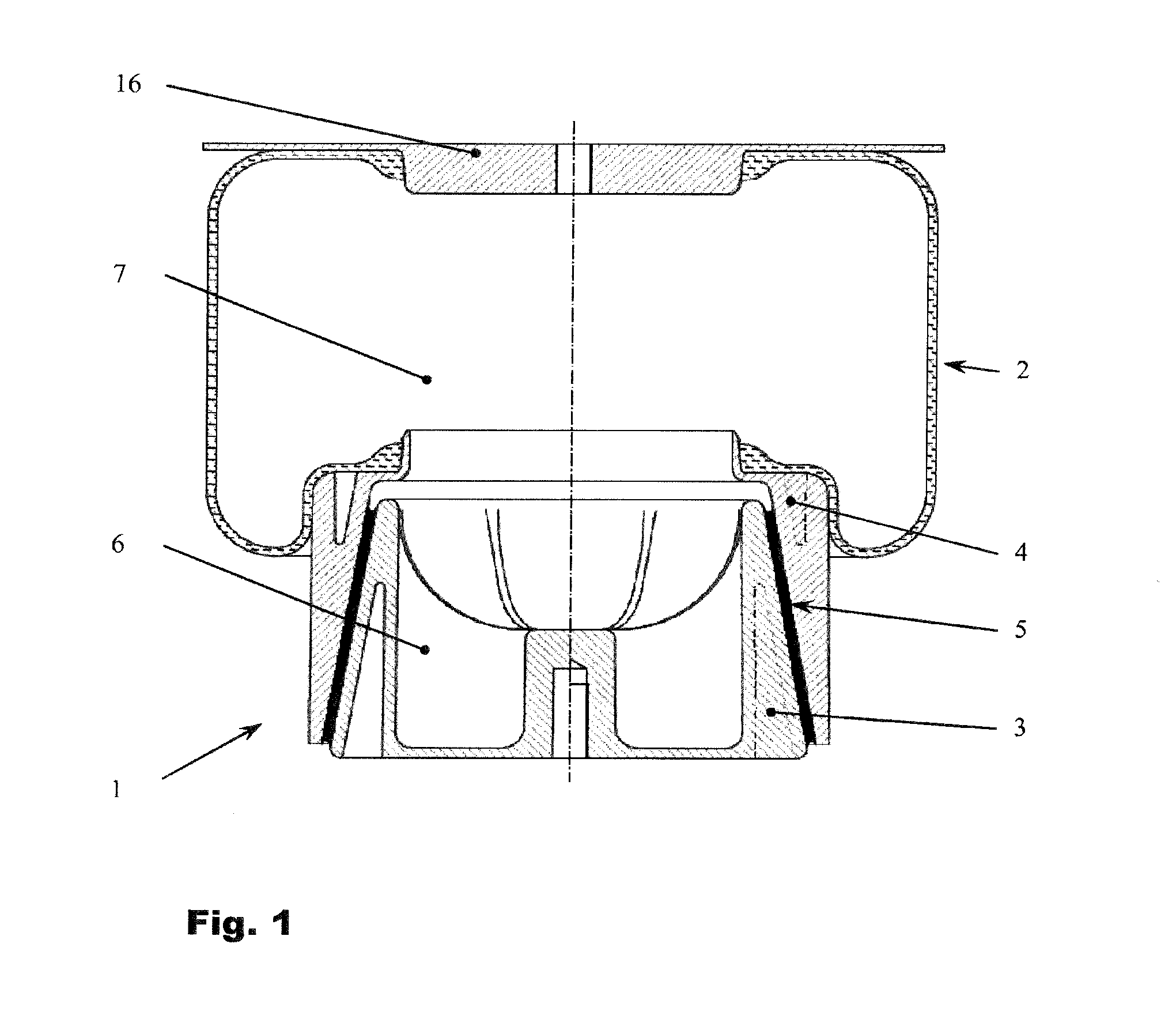
[0031]FIG. 1 shows a roll-off piston 1 according to the invention made of glass fiber reinforced plastic for an air spring rolling-lobe flexible member 2. The air spring rolling-lobe flexible member and the roll-off piston are arranged between the body and the chassis of a vehicle, the body and the chassis not being represented any more specifically here. The air spring rolling-lobe flexible member 2 is closed at its upper end by an air spring cover 16. The cover 16 has an air supply and is connected to the body of the vehicle.

[0032]The roll-off piston 1 is made of two piston parts that are connected to one another, namely, a substantially pot-shaped and rotationally symmetrical lower piston part 3 and an upper piston part 4 formed so as to be complementary thereto. The upper piston part 4 and the lower piston part 3 are fitted one inside the other, with an intermediate layer 5 of elastomeric material arranged therebetween, and thus forming a roll-off piston 1 made up of a layered c...


PUM

PropertyMeasurementUnit
flexibleaaaaaaaaaa
elastomericaaaaaaaaaa
volumeaaaaaaaaaa

Abstract

A roll-off piston is made of plastic for an air spring rolling-lobe flexible member. The roll-off piston and the air spring rolling-lobe flexible member are arranged between a sprung mass and an unsprung mass. The roll-off piston includes a first piston part; a second piston part connected to the first piston part; and, the first and second piston parts being made of a layered composite material of alternating layers of plastic and elastomeric material.

Description

CROSS REFERENCE TO RELATED APPLICATIONS[0001]This application is a continuation application of international patent application PCT / EP2013 / 053867, filed Feb. 27, 2013, designating the United States and claiming priority from German application 10 2012 103 358.7, filed Apr. 18, 2012,and the entire content of both applications is incorporated herein by reference.FIELD OF THE INVENTION[0002]The invention relates to a roll-off piston made of plastic for an air spring rolling-lobe flexible member. The air spring rolling-lobe flexible member and the roll-off piston are arranged between a sprung and an unsprung mass, in particular between the body and the chassis of a vehicle. The roll-off piston has at least two piston parts connected to one another, in particular a substantially pot-shaped and rotationally symmetrical lower piston part and an upper piston part formed so as to be complementary thereto.BACKGROUND OF THE INVENTION[0003]The upper piston part usually has annular profiles and / ...

Claims


Application Information

Patent Timeline
05 Feb 2015
Publication
US20150035213A1
IPC
F16F9/05; B60G11/27
CPC
B60G11/27; F16F9/057
Inventors
STAHMER, REINHARD; RECK, SIEGFRIED