
Video camera and a video receiver of a video monitoring system

a video monitoring system and video camera technology, applied in the field of video cameras and video receivers of video monitoring systems, can solve the problems of uncontrollable delay of one or several cameras, bicycles might be hit, and bicycle drivers can be severely hurt, so as to increase the security of the video monitoring system

Inactive Publication Date: 2015-02-05
APPL SOLUTIONS ELECTRONICS & VISION
View PDF15 Cites 11 Cited by
  • Summary
  • Abstract
  • Description
  • Claims
  • Application Information

AI Technical Summary

Benefits of technology

The present invention provides an apparatus and method for increasing security in a video monitoring system. The invention involves embedding watchdog information data in a sequence of digital images to enhance security against dangers and manipulations. The watchdog information data is transported as payload within data packets, making the data transport more resilient against communication impairments. The use of Ethernet packages or Ethernet frames has the advantage of implementing additional circuitry avoidance. This invention further increases security against failures.

Problems solved by technology

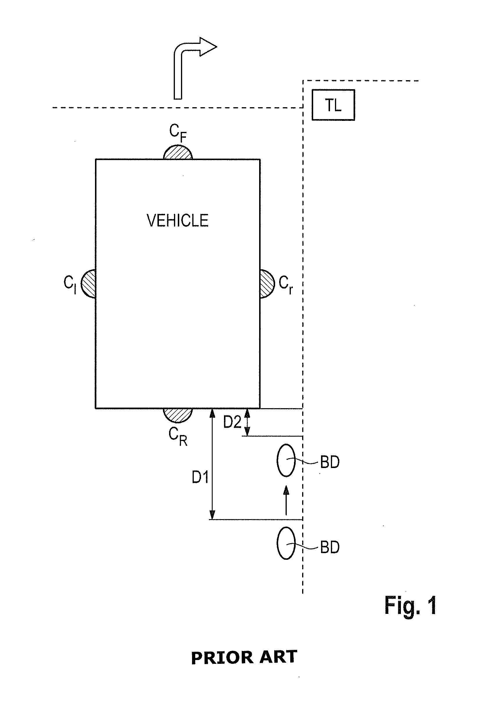
However, if there is a time delay between the generation of the images by the video cameras and the time the driver of the vehicle gets the image displayed on his driver's display, the digital images displayed to the driver do not reflect that the bicycle driver BD has already moved in the meantime much closer to the rear end of the vehicle to a distance D2 as illustrated in FIG. 1.
When in this situation the vehicle turns to the right, the bicycle might be hit by the vehicle and the bicycle driver BD can be severely hurt.
The uncontrolled delay of one or several cameras can be caused by a malfunction of the respective video camera or the video receiver.
Furthermore, a communication channel between the video camera and the video receiver can be interrupted or impaired.
Another possible cause for a picture freeze or an uncontrolled delay can be a processing error of the complex video processing software.

Method used


Image

  • Video camera and a video receiver of a video monitoring system
  • Video camera and a video receiver of a video monitoring system
  • Video camera and a video receiver of a video monitoring system

Examples


Embodiment Construction

[0036]As can be seen in FIGS. 2, 3, a video monitoring system 1 according to an aspect of the present invention comprises at least one video camera 2 connected via a network 3 to a video receiver 4 of the video monitoring system 1, wherein a display 5 can be connected to the video receiver 4. The display 5 shown in FIG. 3 can be for instance a display within a vehicle such as a car, truck or train. The network 3 shown in FIG. 3 can be a local network or data bus as in a vehicle or in another embodiment, a data network such as an internet connecting the video camera 2 to a remote video receiver 4. The network 3 of the video monitoring system 1 shown in FIG. 3 can be a wireless or a wired network.

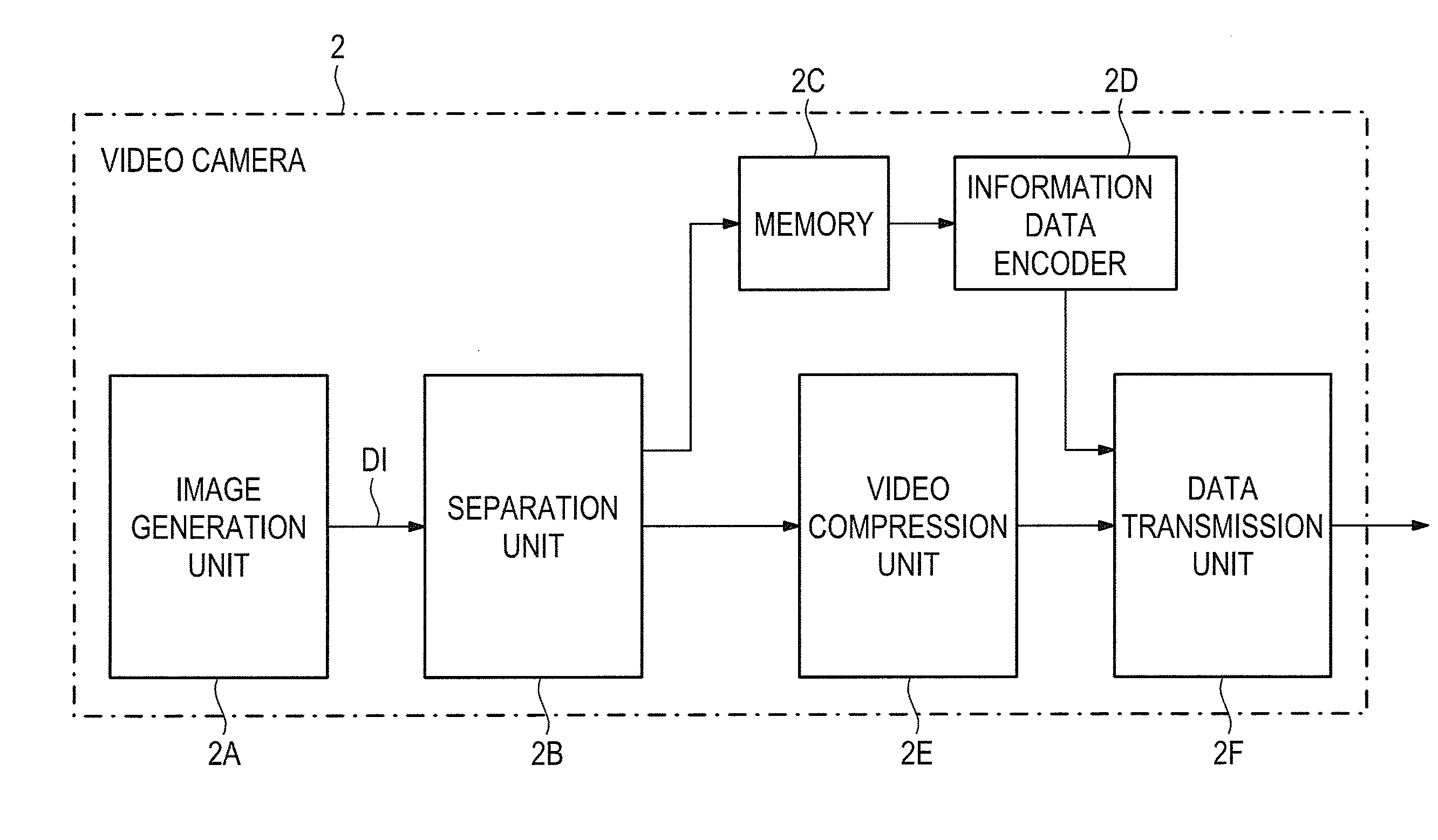
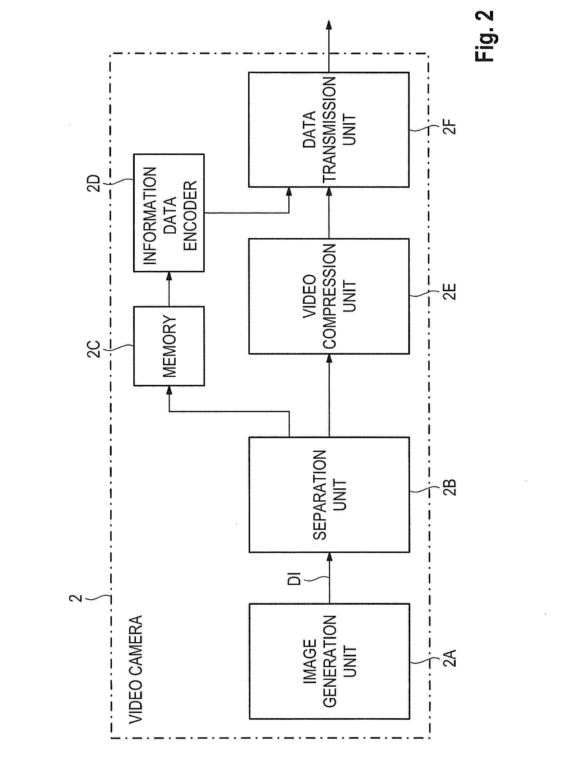
[0037]FIG. 2 shows a block diagram of an exemplary embodiment of the video camera 2 used in the video monitoring system 1 as illustrated in FIG. 3. The video camera 2 shown in FIG. 2 comprises an image generation unit 2A which provides a sequence of digital images DI having watchdog informati...


PUM


Abstract

A video camera of a video monitoring system includes an image generation unit which provides a sequence of digital images (DI) having watchdog information data to supervise the sequence of digital images; an information data encoder adapted to encode the watchdog information data to generate information blocks; a video compression unit adapted to compress the digital images received from the image generation unit to generate compressed digital images consisting of image blocks; a data transmission unit adapted to transmit the generated image blocks received from the video compression unit along with the information blocks generated by the information data encoder.

Description

CROSS REFERENCE TO RELATED APPLICATIONS[0001]This application claims priority to EPO Application No. EP 13179109, filed Aug. 2, 2013, the contents of such application being incorporated by reference herein.FIELD OF THE INVENTION[0002]The invention relates to a video camera and a video receiver of a video monitoring system and in particular to a video watchdog concept for a video camera used in a video monitoring system which can be employed in an automotive surround view system.BACKGROUND OF THE INVENTION[0003]In many applications, video cameras are used in a video monitoring system. Video cameras are for instance used in airport security or traffic monitoring. Video cameras can also be used in wrap-around top view systems within automotive applications. A vehicle such as a truck can be equipped with cameras mounted on the truck to report images from different directions. A conventional top view system can combine images of different cameras for helping a driver to improve his visib...

Claims


Application Information

Patent Timeline
IPC IPC(8): H04N7/18H04N5/44
CPCH04N5/44H04N7/183
Inventor SCHREPFER, JORGKELLAWAY, TREVOR
Owner APPL SOLUTIONS ELECTRONICS & VISION
Learn More