Arrangement and method for converting an input signal into an output signal and for generating a predefined transfer behavior between said input signal and said output signal

a technology of input signal and output signal, which is applied in the direction of transducer protection circuits, electrical transducers, transducer circuits, etc., can solve the problems of nonlinearity, harmonic distortion and other symptoms of nonlinearity, measurement does not give a complete description of nonlinearity transfer behavior, and the nonlinearity inherent in the electro-magnetic principle is a source of signal distortion, etc., to achieve a feed-forward structure which is always stabl

Active Publication Date: 2015-02-05
KLIPPEL WOLFGANG
View PDF2 Cites 150 Cited by
  • Summary
  • Abstract
  • Description
  • Claims
  • Application Information

AI Technical Summary

Benefits of technology

[0007]The invention discloses a measurement technique which identifies all free parameters P of the extended model by monitoring at least one state variable of the transducer. The direct measurement of the armature position x or other mechanical or acoustical signals require a cost effective sensor. The hardware requirements can be reduced by monitoring an electrical signal at the terminals and by using the model for the identification of mechanical parameters. Optimal values of the free parameters P of the model are estimated by minimizing a cost function that describes the mean squared error between predicted and measured state variable. This measurement can be realized as an adaptive process while reproducing an arbitrary stimulus. The measurement is immune against ambient noise as found in a production environment or in the target application. The measurement technique evaluates the accuracy of the modeling by comparing the theoretical and real behavior of the transducer.
[0011]The control system uses a state predictor to synthesize the states of the transducer under the condition that undesired nonlinear distortions are compensated in the output signal. This results in a control law with a feed-forward structure which is always stable. Any time delay may be added between the measurement system and the controller because the transferred parameter vector P changes slowly over time. The invention avoids any feedback of state variables from the measurement system to the controller.
[0012]The control system can also be used for generating a DC component at the terminals of the transducer which moves the armature actively to the symmetry point xs and reduces the offset xoff actively. This feature is very important for stabilizing transducers which have a low mechanical stiffness and which are desired for closed-box systems with a small intended leakage to cope with static air pressure variations.
[0013]According to the invention the controller provides a protection against high amplitudes of the input signal causing a thermal and mechanical overload of the transducer which may cause excessive distortion in the output signal and a damage of the unit. The protection system uses the state vector x synthesized by a state predictor which corresponds to the state variables (e.g. armature position x, input current i) of the transducer to detect an overload situation. The limits of the permissible working range such as the maximal displacement xlim may be automatically derived from the parameter vector P provided by the measurement system.

Problems solved by technology

The nonlinearities inherent in the electro-magnetic principle are a source of signal distortion.
Straightforward distortion measurement techniques reveal harmonic distortion and other symptoms of nonlinearities inherent in this transducer.
However, the results of these measurements do not give a complete description of the nonlinear transfer behavior but depend on the particular properties of the excitation stimulus.
The theory developed for electro-dynamical transducers is not applicable for electro-magnetic transducers.
The prior art has not disclosed a measurement technique for identifying the free parameters of this model applicable to real transducers.

Method used


Image

  • Arrangement and method for converting an input signal into an output signal and for generating a predefined transfer behavior between said input signal and said output signal
  • Arrangement and method for converting an input signal into an output signal and for generating a predefined transfer behavior between said input signal and said output signal
  • Arrangement and method for converting an input signal into an output signal and for generating a predefined transfer behavior between said input signal and said output signal

Examples


Embodiment Construction

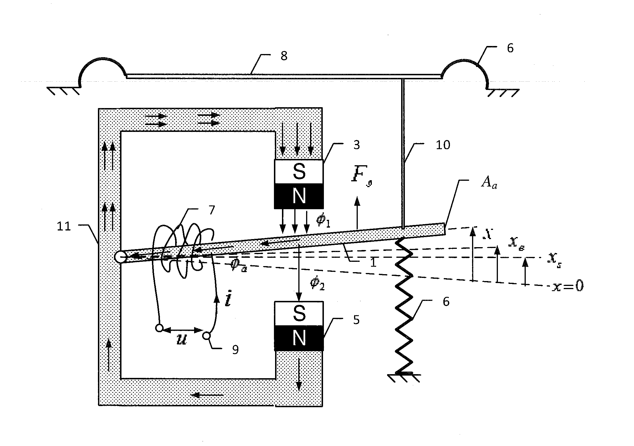
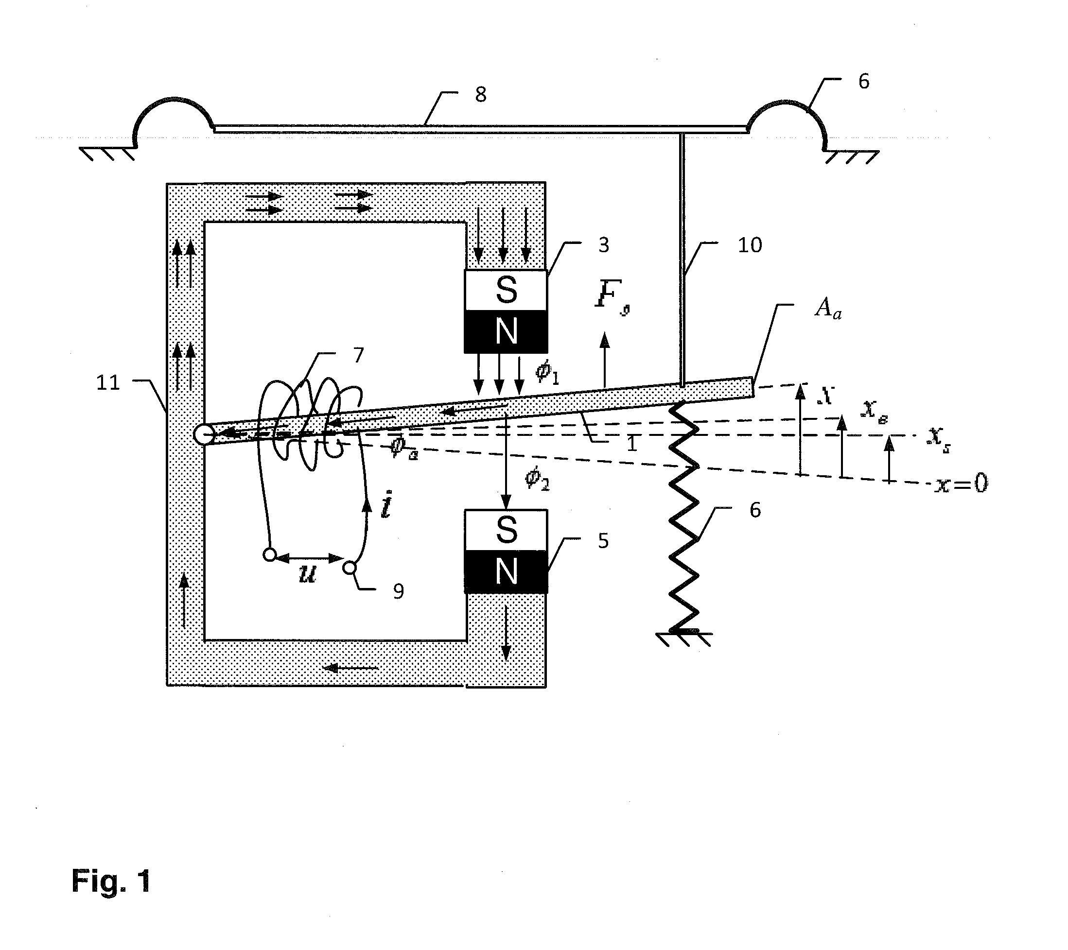
[0029]The derivation of the theory is illustrated by the example of the balanced-armature device as shown in FIG. 1 but may be applied to other types of the electro-magnetic transducer in a similar way. The armature 1 is placed in the air gap between the magnets 3 and 5 which are part of a magnetic circuit 11. A coil 7 placed at a fixed position generates a magneto-motive force Ni, depending on the number N of wire turns and input current i at the terminals 9. The mechanical suspension 6 determines the rest position of the armature and the driving rod 10 is connected to the diaphragm 8.

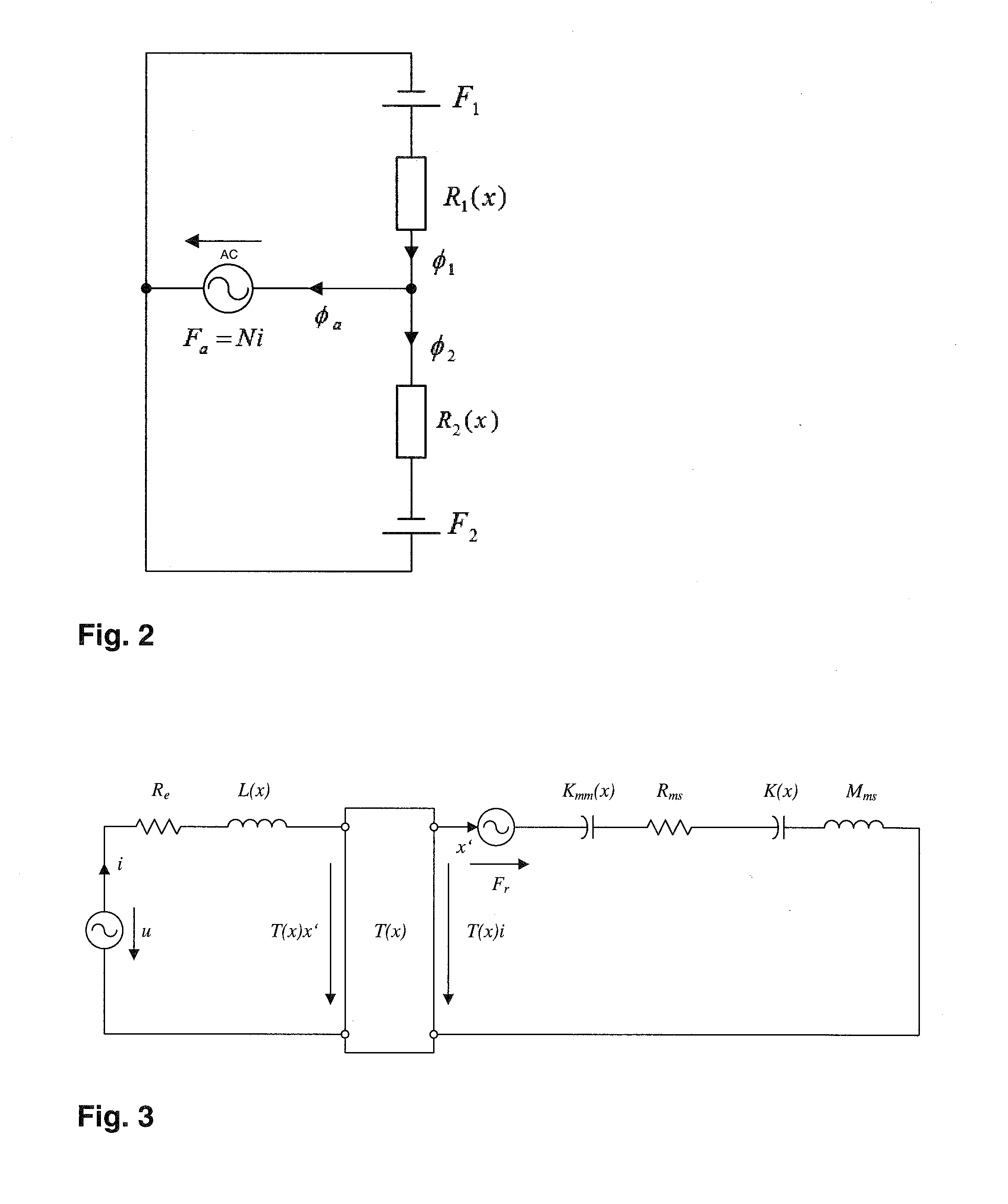
[0030]The model, as disclosed by F. V. Hunt in the above mentioned prior art, is based on the assumptions that the magnets 3 and 5 have the same magneto-motive force

Fm=F1=F2  (1)

and the magnetic reluctances R1(x) and R2(x) of the air in the upper and lower gap are much larger than any other reluctance in the iron path giving the simplified magnetic circuit in FIG. 2. Then the magnet fluxes φ1 and φ2 i...


PUM


Abstract

An arrangement and method for converting an input signal z(t) into a mechanical or acoustical output signal p(t) comprising an electro-magnetic transducer using a coil at a fixed position and a moving armature, a sensor, a parameter measurement device and a controller. The parameter measurement device identifies parameter information P of an nonlinear model of the transducer considering and the saturation and the geometry of the magnetic elements. A diagnostic system reveals the physical causes of signal distortion and generates information for optimizing the design and manufacturing process of this transducer. The controller compensates for nonlinear signal distortion, stabilizes the rest position of the armature and protects the transducer against mechanical and thermal overload.

Description

FIELD OF THE INVENTION[0001]The invention generally relates to an Arrangement and method for converting an input signal into an output signal and for generating a predefined transfer behavior between said input signal and said output signal.BACKGROUND OF THE INVENTION[0002]The invention generally relates to an arrangement and a method for identifying the parameters of a nonlinear model of an electro-magnetic transducer and for using this information to correct the transfer characteristics of this transducer between input signal v and output signal p by changing the properties of the electro-magnetic transducer in design, manufacturing and by compensating actively undesired properties of said transducer by electric control. The electro-magnetic transducer may be used as an actuator (e.g. loudspeaker) or as a sensor (e.g. microphone) having an electrical input or output, respectively.[0003]Most loudspeakers, headphones and other electro-acoustical devices use an electro-dynamical tran...

Claims


Application Information

Patent Timeline
Patent Type & Authority Applications(United States)
IPC IPC(8): H04R3/00
CPCH04R3/007H04R11/00
Inventor KLIPPEL, WOLFGANG
Owner KLIPPEL WOLFGANG
Why Eureka
Try Eureka