
Composite propeller blade structure

a propeller blade and composite technology, applied in the direction of wind motors, wind motors with perpendicular air flow, motors, etc., can solve the problems of inability to carry out further performance boosting, and achieve the effect of effective boosting the performance of the propeller blade, reasonable production cost, and better energy consumption efficiency

Inactive Publication Date: 2015-02-05
APPLIED THERMAL FLUID ANALYSIS CENT LIMITED LIABILITY
View PDF14 Cites 12 Cited by
  • Summary
  • Abstract
  • Description
  • Claims
  • Application Information

AI Technical Summary

Benefits of technology

This patent is for a new type of propeller blade that is made from a combination of materials to improve its performance. This design can make the blade more energy efficient, cost-effective, and easy to use. It will provide better performance and efficiency for those who use it.

Problems solved by technology

The existed technology for adjusting the dimension and angle of the blade for achieving the best performance has faced a bottleneck, so further performance boosting is unable to be carried out.

Method used


Image

  • Composite propeller blade structure
  • Composite propeller blade structure
  • Composite propeller blade structure

Examples


Embodiment Construction

[0019]Preferred embodiments of the present invention will be described with reference to the drawings.

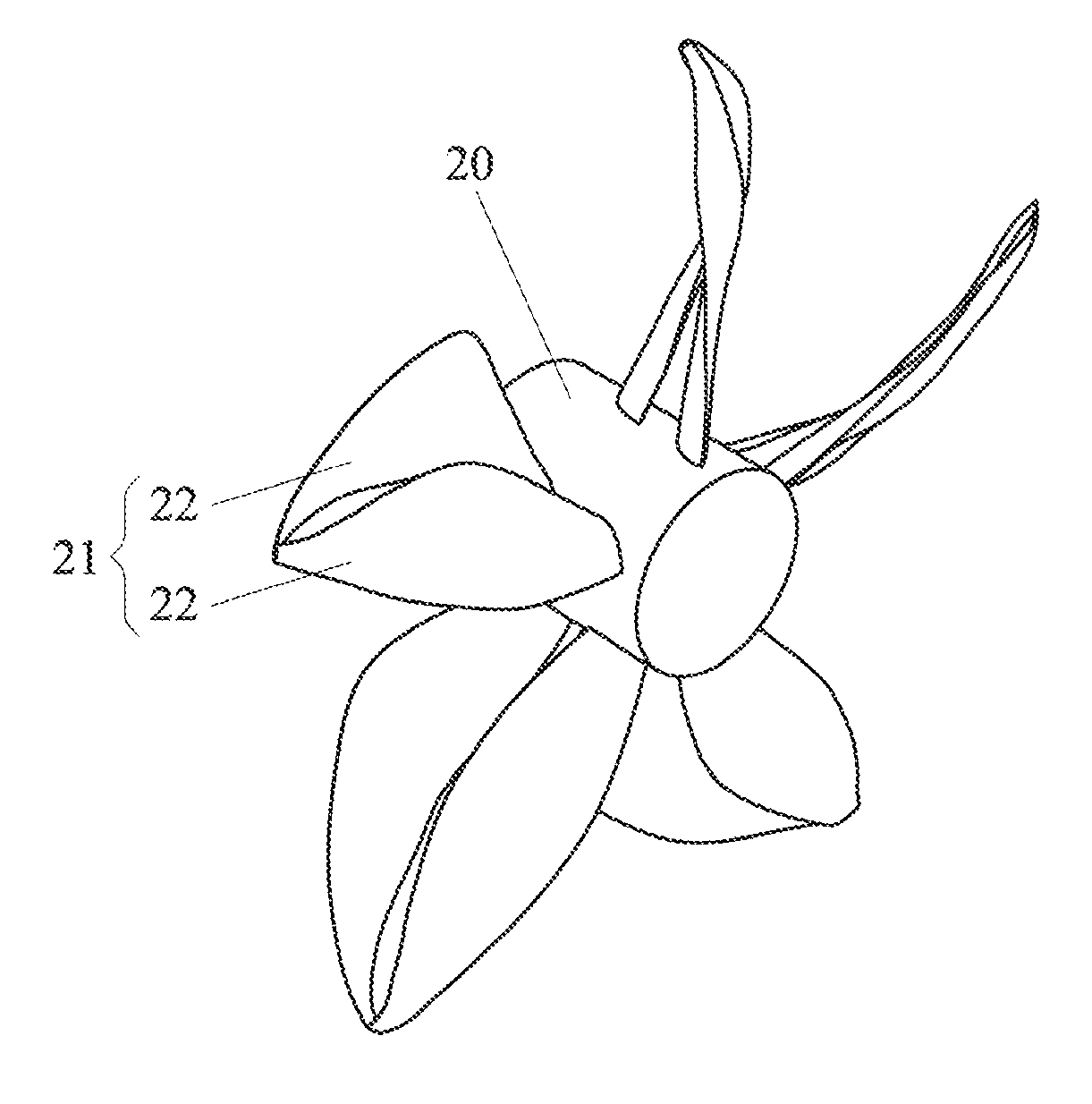
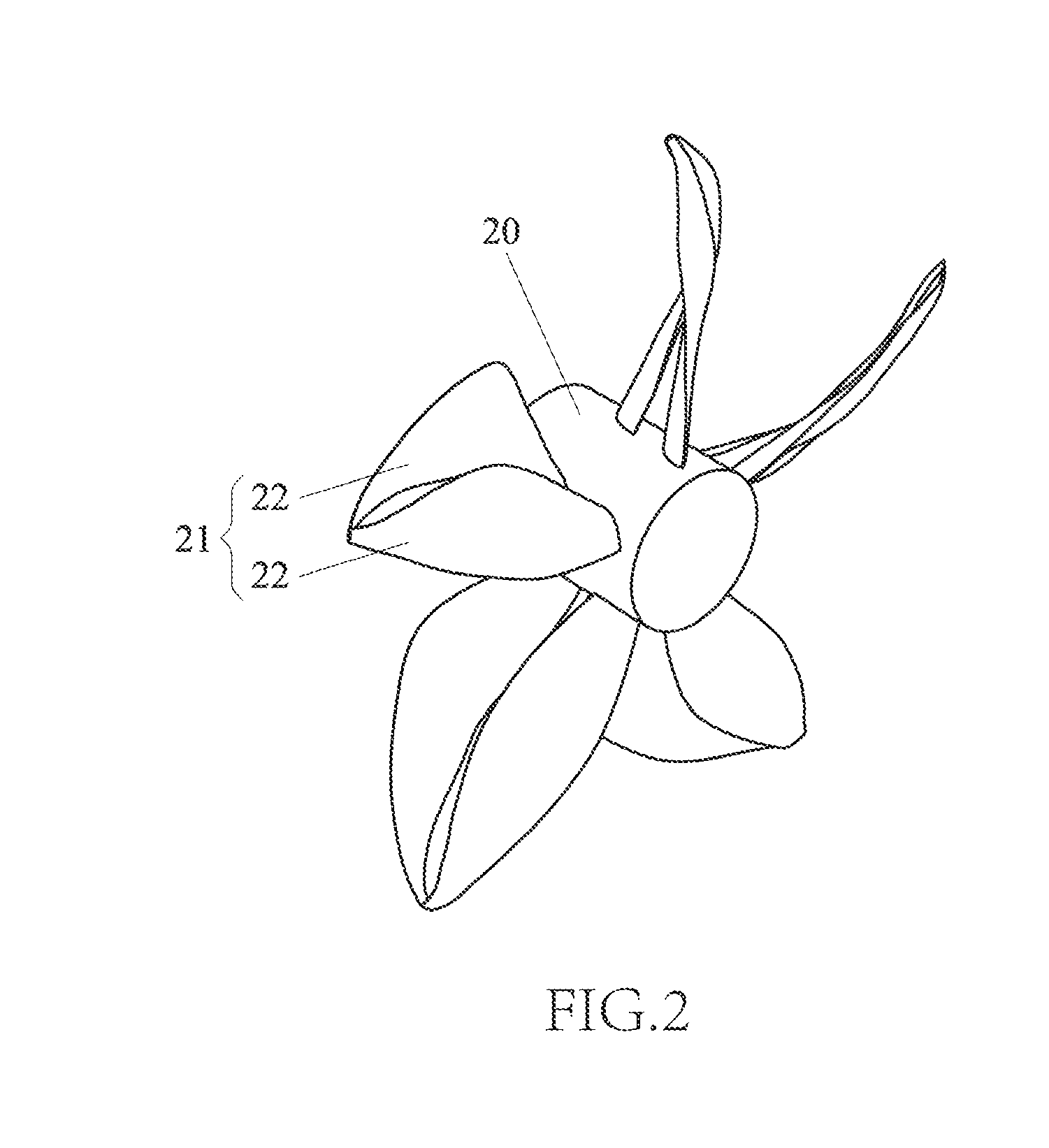
[0020]The present invention discloses a composite propeller blade structure including at least a rotation shaft and a rotation surface correspondingly formed relative to the rotation shaft, and plural blades are formed on the rotation surface, which is characterized in that: each of the blades is composed of plural blade units, wherein the distance between any two adjacent blades is greater than the distance between any two adjacent blade units, and the suction side of the blade unit at the downstream is located in the position closer to the pressure side of the blade unit at the upstream rather than the suction side of the blade unit at the upstream. Accordingly, in the equivalent radius cross section of each of the blades, the installed location of a front edge of the blade unit at the downstream is defined as following: in the rotation axial direction, which is located behind a r...


PUM


Abstract

A composite propeller blade structure includes at least a rotation shaft and a rotation surface on which plural blades are formed, and characterized in that: each of the blades is composed of plural blade units; and in the equivalent radius cross section of each of the blades, the installed location of a front edge of the blade unit at the downstream is defined as following: in the rotation axial direction, which is located behind a rear edge of the adjacent blade unit at the upstream, and the maximum distance thereof is not greater than 25% of the radius of the adjacent blade unit at the upstream; and in the circumferential direction, located at the pressure surface side defined on the nose-trail line of the adjacent blade unit at the upstream, and the maximum range thereof is not greater than (360° / 2N), wherein N is the quantity of the blades.

Description

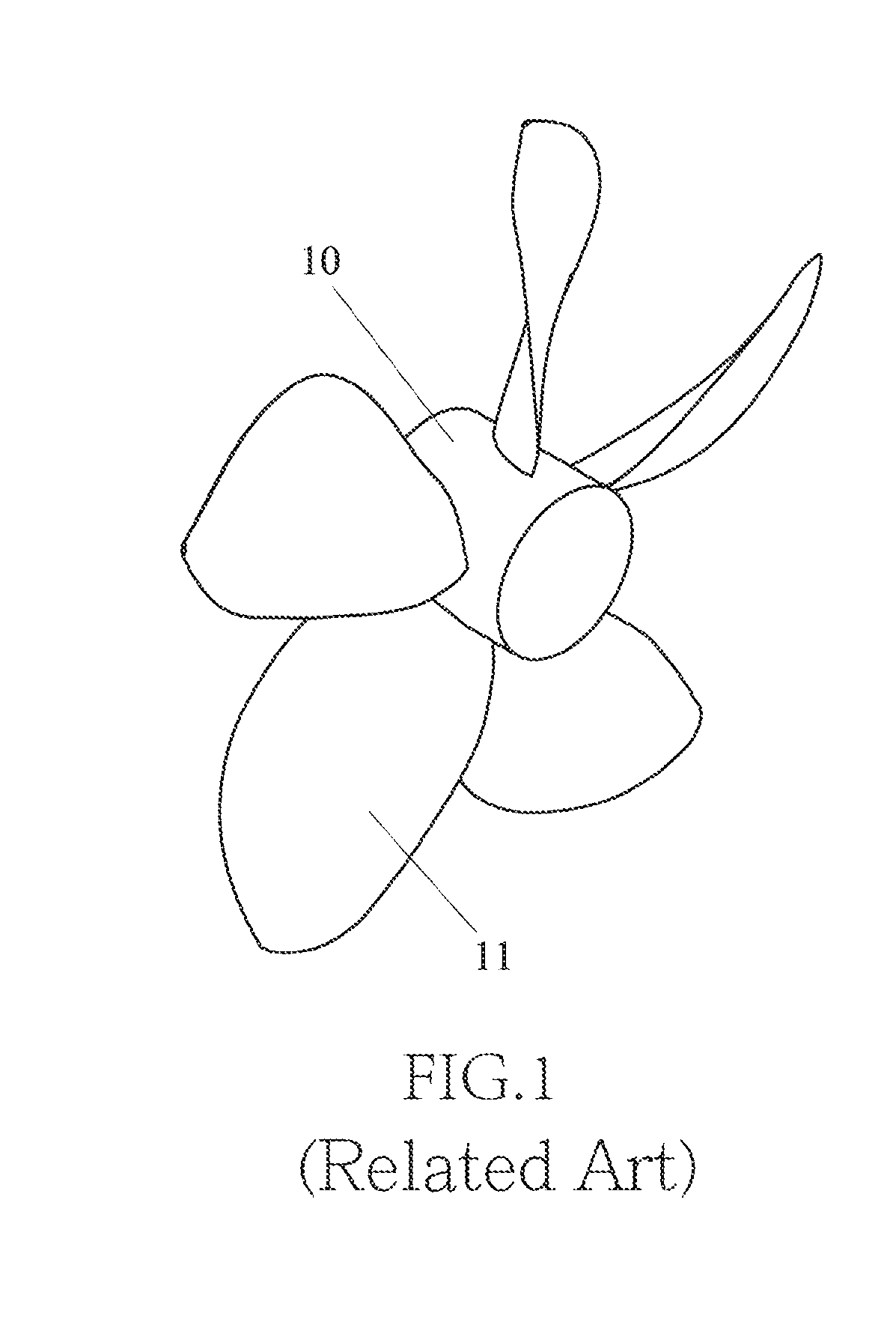
BACKGROUND OF THE INVENTION[0001]1. Field of the Invention[0002]The present invention relates to a propeller blade used in a liquid fluid, especially to a composite propeller blade structure.[0003]2. Description of Related Art[0004]A propeller blade is commonly used in various fields, including being applied as a thruster in a boat or a submarine for the purpose of driving. As such, the performance of a propeller blade structure being boosted plays an important role regarding to cost controlling, work efficiency and energy saving.[0005]A typical propeller blade structure includes at least a rotation shaft and a rotation surface correspondingly formed relative to the rotation shaft, and plural blades having the same configuration are formed on the rotation surface. The existed technology for adjusting the dimension and angle of the blade for achieving the best performance has faced a bottleneck, so further performance boosting is unable to be carried out.[0006]Accordingly, the presen...

Claims


Application Information

Patent Timeline
Patent Type & Authority Applications(United States)
IPC IPC(8): B63H1/26
CPCB63H1/26B63H1/265
Inventor TZENG, YIH-WEI
Owner APPLIED THERMAL FLUID ANALYSIS CENT LIMITED LIABILITY
Learn More