Control device for internal combustion engine

a control device and internal combustion engine technology, applied in the direction of engines, machines/engines, mechanical apparatus, etc., can solve the problems of clogging difficult to process deposited metal, exhaust gas to strike a particular portion, etc., to facilitate the warming of the exhaust gas purification catalyst

Inactive Publication Date: 2015-02-12
TOYOTA JIDOSHA KK
View PDF0 Cites 11 Cited by
  • Summary
  • Abstract
  • Description
  • Claims
  • Application Information

AI Technical Summary

Benefits of technology

[0007]It is an object of the present invention to provide a control device for an internal combustion engine that accurately limits the local clogging of an exhaust gas purification catalyst.Means for Solving the Problem
[0009]In this structure, when the engine is running, the open degree of the wastegate valve changes between the minimum open degree and a value greater than the minimum open degree. This changes the flow direction of the exhaust gas discharged through the port so that the flowing direction is not fixed. Therefore, the exhaust gas is restricted from continuously and locally striking the inlet of the exhaust gas purification catalyst, and the exhaust gas is allowed to strike a larger area of the inlet. This limits local clogging of the exhaust gas purification catalyst. Under this situation, the flow rate of the exhaust gas that flows through the port remains unchanged while the open degree of the wastegate valve changes. This accurately limits local clogging of the exhaust gas purification catalyst.
[0013]In this structure, the open degree of the wastegate valve is controlled based on the engine running state, and the boost pressure is controlled accordingly in a preferred manner. Further, in the above structure, when the open degree of the wastegate valve, which is set based on the engine running state, is greater than or equal to the minimum open degree, the open degree of the wastegate valve changes in a range greater than or equal to the minimum open degree. This accurately limits local clogging of the exhaust gas purification catalyst without hindering the control of the boost pressure.
[0015]In an internal combustion engine installed in a vehicle, a metal such as manganese included in an exhaust gas tends to be deposited on an exhaust gas purification catalyst especially when the vehicle is travelling at a high constant speed. In such a case, the open degree of the wastegate valve is set to be greater than or equal to the minimum open degree. Therefore, the above structure accurately limits local deposition of a metal such as manganese on the exhaust gas purification catalyst.
[0017]Due to limitations imposed on the layout of the exhaust system, an internal combustion engine may include an exhaust passage in which a connector is bent between a turbine and an exhaust gas purification catalyst. In the above structure, the port of a wastegate mechanism, which is aligned with the outlet of the turbine, and the exhaust gas purification catalyst are located at opposite sides of the rotation axis of the turbine wheel. Additionally, the valve is a flap-type valve that opens in the downstream direction of the exhaust gas about a pivot point located at a side of the port opposite to the rotation axis. Thus, the exhaust gas directly strikes the exhaust gas purification catalyst when the valve opens. This facilitates the warming of the exhaust gas purification catalyst. When the present invention is applied to an internal combustion engine having such a structure, exhaust gas strikes a larger area of the inlet of the exhaust gas purification catalyst. Consequently, this limits local clogging of the exhaust gas purification catalyst.

Problems solved by technology

It is difficult to process the deposited metal, which may clog the exhaust gas purification catalyst.
Due to limitations imposed on the layout of the exhaust system, there is a tendency for exhaust gas to strike a particular portion at the inlet of the exhaust gas purification catalyst.
Thus, local clogging may occur.
This may cause early deterioration of the performance of the exhaust gas purification catalyst.

Method used


Image

  • Control device for internal combustion engine
  • Control device for internal combustion engine
  • Control device for internal combustion engine

Examples


Embodiment Construction

[0021]One embodiment of the present invention that is employed as a control device for an internal combustion engine installed in a vehicle will now be described with reference to FIGS. 1 to 4.

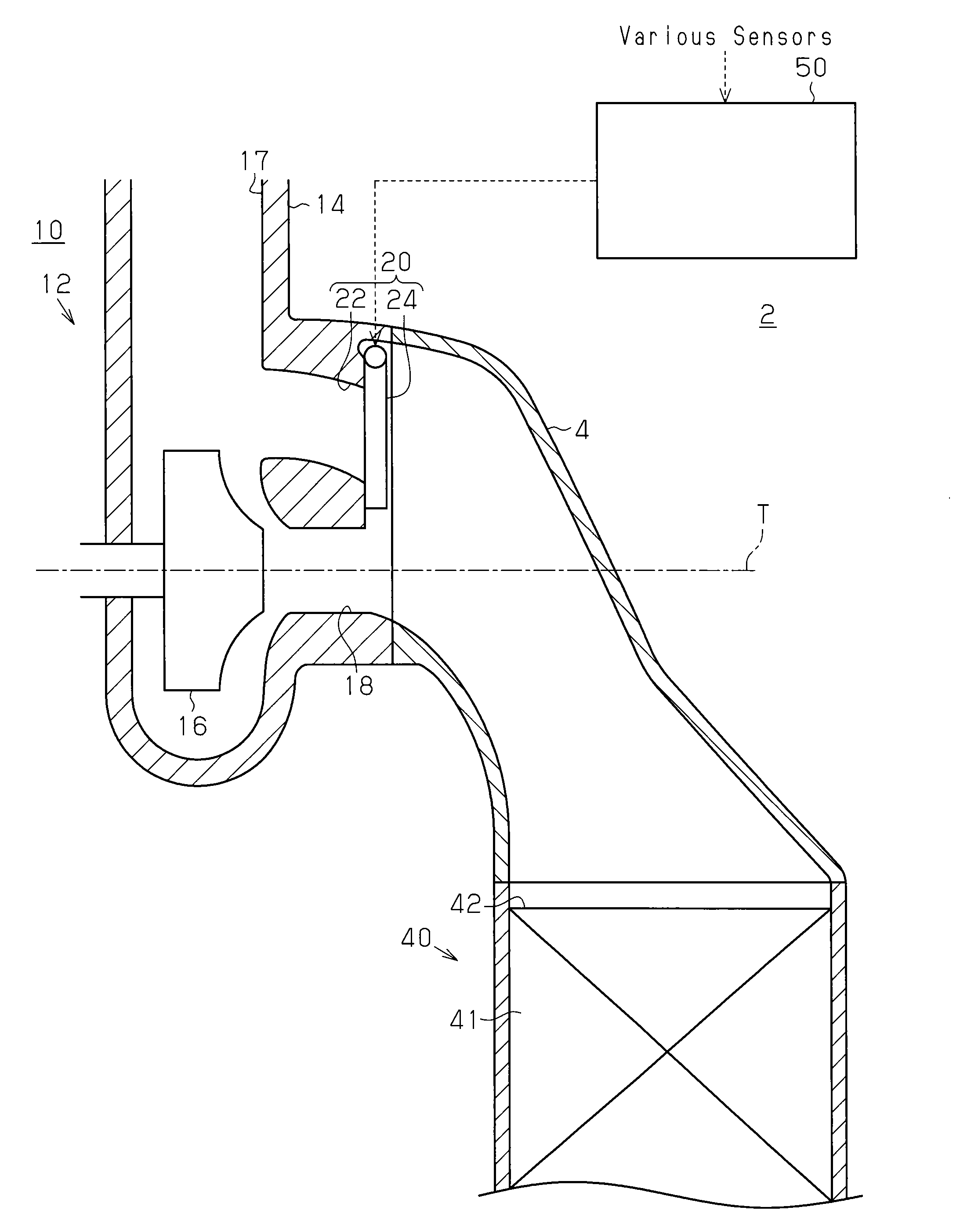
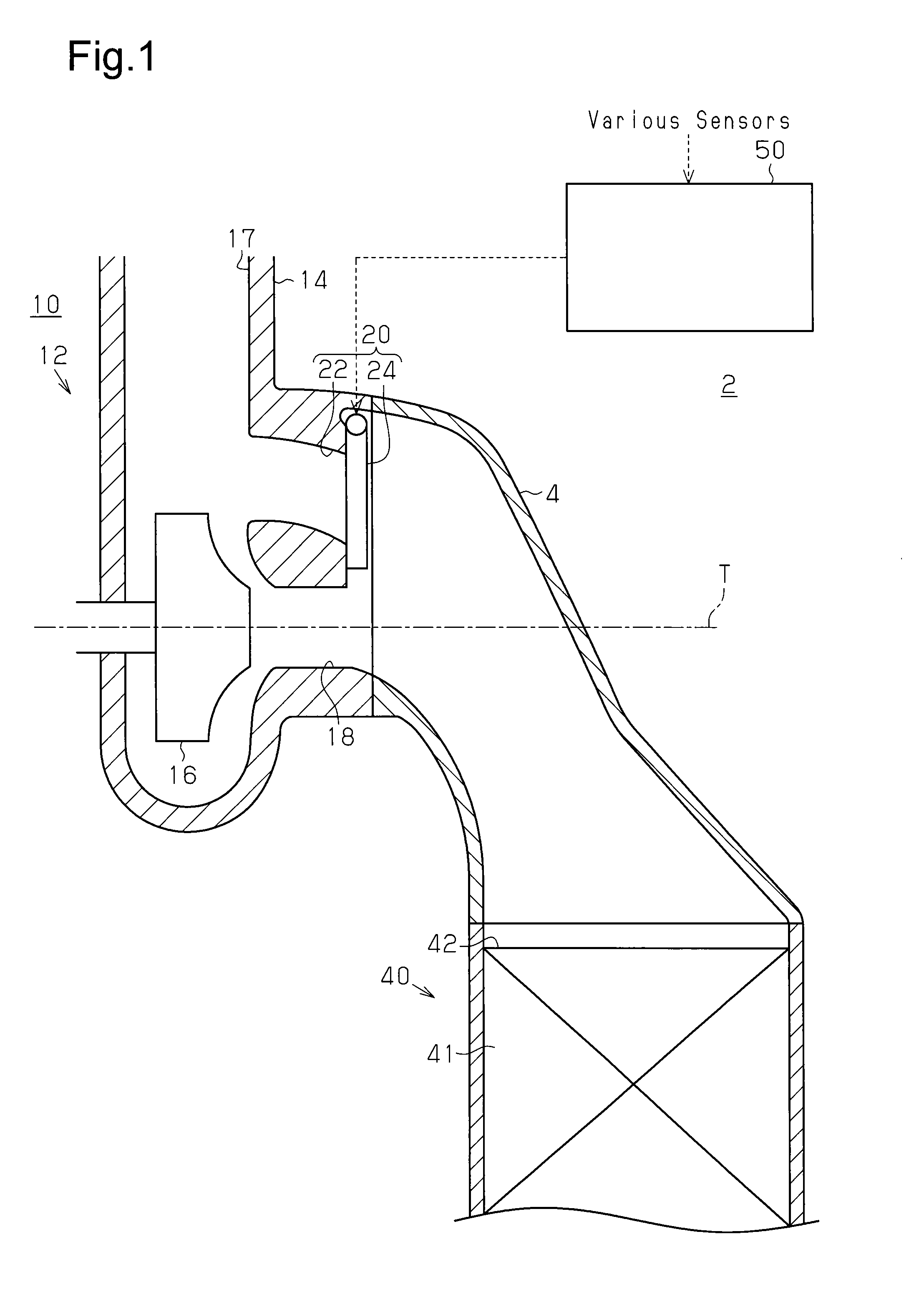
[0022]FIG. 1 shows the cross-sectional structure of an exhaust passage where a turbine is located in an internal combustion engine of the present embodiment.

[0023]As shown in FIG. 1, an internal combustion engine is a driving source for a vehicle, and an exhaust passage 2 of the internal combustion engine includes, in order from the upstream side, a turbine 12, a connector 4, and a catalytic converter 40.

[0024]The turbine 12 includes a turbine housing 14 and a turbine wheel 16, which is encased in the turbine housing 14. The rotation axis T of the turbine wheel 16 extends in the right-left direction of the drawing. A compressor wheel is axially connected to the turbine wheel 16. The compressor wheel is rotationally driven when the turbine wheel 16 is rotationally driven.

[0025]An inlet 17 of th...


PUM


Abstract

The minimum value for the degree of opening of a wastegate valve, wherein the flow volume of exhaust air flowing via a wastegate port when the degree of opening of the wastegate valve is changed toward the open side stops increasing, is defined as a first prescribed degree of opening An electronic control device controls the degree of opening of the wastegate valve on the basis of the engine operating state, and when the vehicle is running steadily at a high speed, that is, when the degree of opening of the wastegate valve which has been set on the basis of the engine operating state is equal to or greater than the first prescribed degree of opening, the degree of opening of the wastegate valve is varied between values equal to or greater than the first prescribed degree of opening.

Description

TECHNICAL FIELD[0001]The present invention relates to a control device for an internal combustion engine that includes a turbocharger.BACKGROUND ART[0002]An internal combustion engine that includes a turbocharger (hereinafter, forced induction device) is known in the art (for example, refer to patent document 1). A forced induction device includes a turbine and a compressor, which is driven by the turbine. The turbine includes a turbine housing, which is arranged in an exhaust passage, and a turbine wheel, which is encased in the turbine housing.[0003]Additionally, the forced induction device includes a wastegate mechanism that allows exhaust gas to bypass the turbine wheel and be discharged. The wastegate mechanism includes a wastegate port that bypasses the turbine wheel and a wastegate valve that opens and closes the wastegate port. For example, when the pressure of the exhaust gas delivered to the turbine wheel is greater than or equal to a predetermined value, the exhaust gas i...

Claims


Application Information

Patent Timeline
Patent Type & Authority Applications(United States)
IPC IPC(8): F02B37/18F01N3/18
CPCF01N3/18F02B37/183F01N3/2006F01N3/2892F01N5/04F01N13/08F01N2260/06F01N2340/06F01N2900/0422F01N2900/08F02B37/18F02B37/22Y02T10/12Y02A50/20
Inventor MATSUI, HIROKI
Owner TOYOTA JIDOSHA KK
Why Eureka
Try Eureka