Vehicle air conditioning apparatus

Active Publication Date: 2015-02-12
SANDEN CORP
View PDF3 Cites 27 Cited by
  • Summary
  • Abstract
  • Description
  • Claims
  • Application Information

AI Technical Summary

Benefits of technology

[0030]According to the present invention, it is possible to reduce the difference in temperature between the refrigerant flowing from upstream of the radiator and the refrigerant flowing from downstream of the radiator in the refrigerant flow direction. By this means, it is possible to prevent temperature variations of the air after a heat exchange in the radiator, and therefore to reliably control the temperature of the air supplied to the vehicle interior.
[0031]In addition, according to the present invention, during the cooling and dehumidifying operation, it is possible to secure the amount of heating to heat the air blowing to the vehicle interior by regulating the quantity of heat release in the radiator. Therefore, it is possible to ensure that the temperature of the a

Problems solved by technology

Generally, an electric car uses an electric motor as a power source, and it is difficult to acquire the exhaust heat that can heat the air by u

Method used


Image

  • Vehicle air conditioning apparatus
  • Vehicle air conditioning apparatus
  • Vehicle air conditioning apparatus

Examples


Example

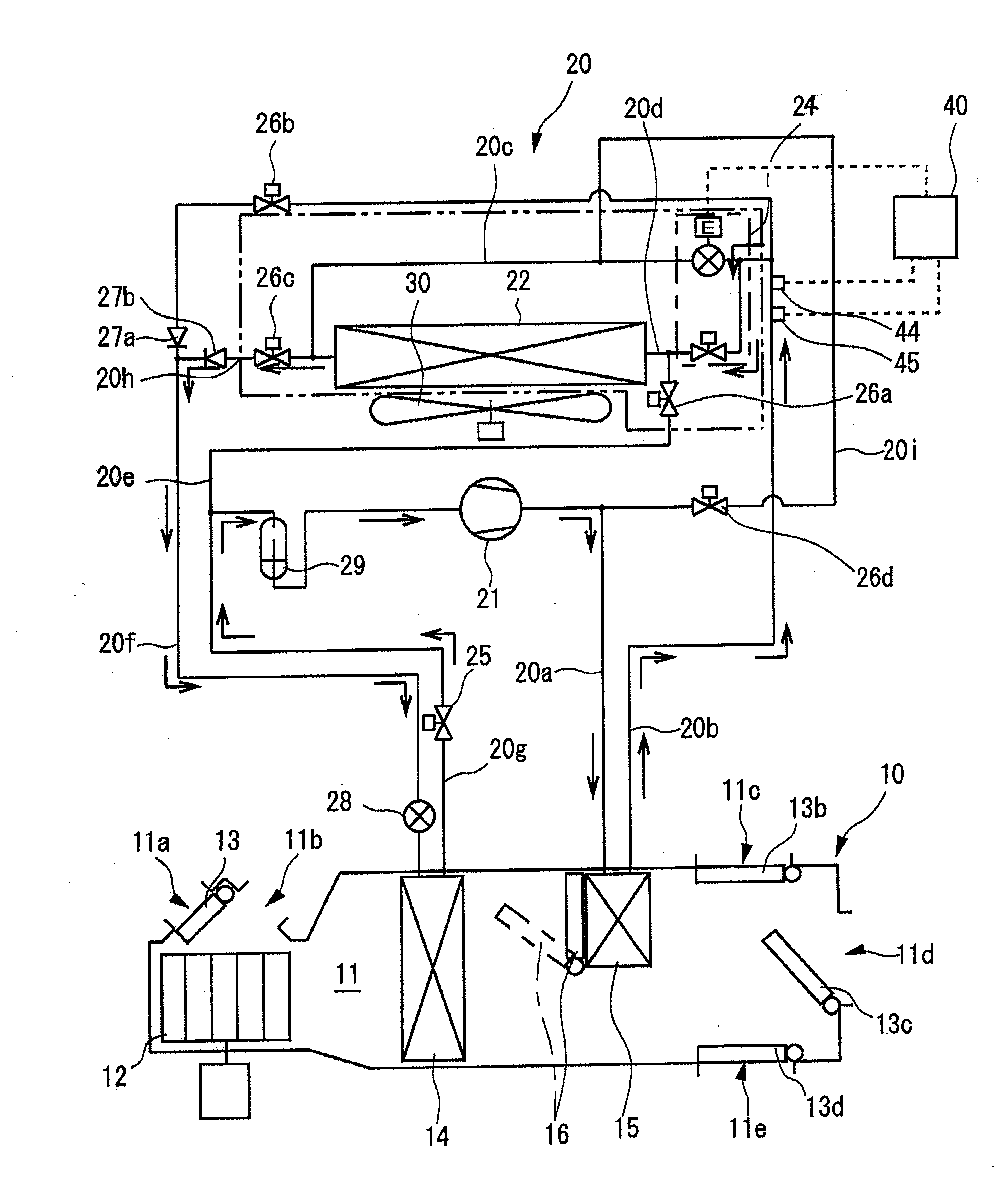
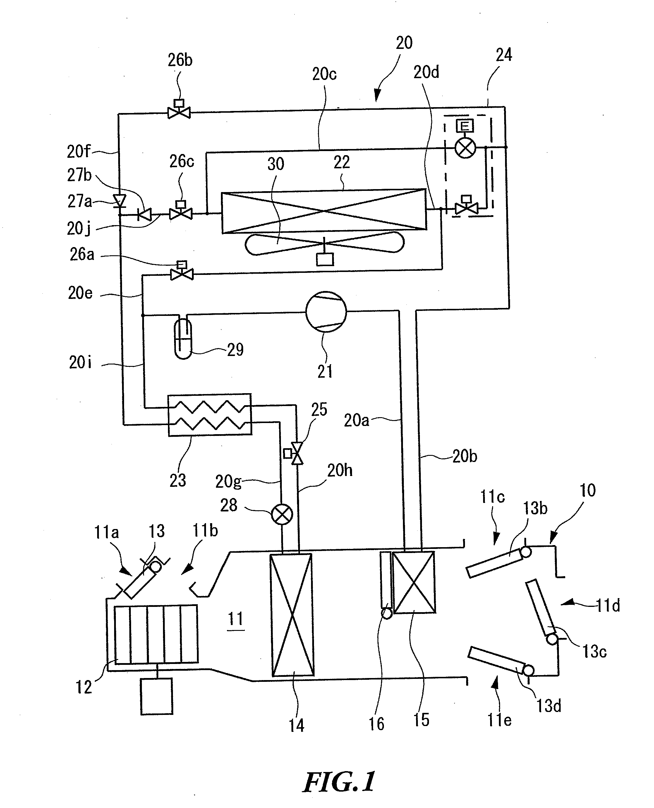
[0098]FIG. 1 to FIG. 10 show Embodiment 1 of the present invention.

[0099]As shown in FIG. 1, the vehicle air conditioning apparatus according to the present invention includes an air conditioning unit 10 provided in the vehicle interior, and a refrigerant circuit 20 formed across the vehicle interior and the outdoor.

[0100]The air conditioning unit 10 includes an air flow passage 11 that allows the air to be supplied to the vehicle interior to pass through. An outdoor air inlet 11a and an indoor air inlet 11b are provided in the first end side of the air flow passage 11. The outdoor air inlet 11a is configured to allow the outdoor air to flow into the air flow passage 11, and the indoor air inlet 11b is configured to allow the indoor air to flow into the air flow passage 11. Meanwhile, a foot outlet 11c, a vent outlet 11d and a defroster outlet 11e are provided in the second end side of the air flow passage 11. The foot outlet 11c is configured to allow the air flowing through the ai...

Example

[0180]FIG. 11 shows Embodiment 2. Here, the same components are assigned the same reference numerals as in the above-described embodiment.

[0181]In the vehicle air conditioning apparatus according to the present embodiment, the controller 40 performs an expansion part control process as shown in the flowchart in FIG. 11 with the same configuration as in Embodiment 1.

[0182](Step S41)

[0183]In step S41, the CPU determines whether the operation is the heating operation or the heating and dehumidifying operation. When determining that the operation is one of the heating operation and the heating and dehumidifying operation, the CPU moves the step to step S42. On the other hand, when determining that the operation is neither the heating operation nor the heating and dehumidifying operation, the CPU ends the expansion part control process.

[0184](Step S42)

[0185]In the step S42, the CPU calculates superheat SH of the refrigerant based on the temperature Tlp detected by the low-pressure refrig...

Example

[0211]FIGS. 13 to 29 show Embodiment 3 of the present invention.

[0212]As shown in FIG. 13, the vehicle air conditioning apparatus according to the present invention includes the air conditioning unit 10 provided in the vehicle interior, and the refrigerant circuit 20 formed across the vehicle interior and the outdoor.

[0213]The air conditioning unit 10 includes the air flow passage 11 that allows the air to be supplied to the vehicle interior to pass through. The outdoor air inlet 11a and the indoor air inlet 11b are provided in the first end side of the air flow passage 11. The outdoor air inlet 11a is configured to allow the outdoor air to flow into the air flow passage 11, and the indoor air inlet 11b is configured to allow the indoor air to flow into the air flow passage 11. Meanwhile, the foot outlet 11c, the vent outlet 11d and the defroster outlet 11e are provided in the second end side of the air flow passage 11. The foot outlet 11c is configured to allow the air flowing thro...


PUM


Abstract

A vehicle air conditioning apparatus is provided that can prevent temperature variations of the air after the heat exchange in a radiator to reliably control the temperature of the air supplied to the vehicle interior. During the heating operation and the heating and dehumidifying operation, target degree of supercooling SCt when target air-blowing temperature TAO is a predetermined temperature or higher is set to SCt1 that is greater than SCt2 when the target air-blowing temperature TAO is lower than the predetermined temperature. When amount of air Ga supplied from indoor fan 12 is lower than a predetermined value, the target degree of supercooling SCt is corrected, which is set such that the degree of supercooling is lower than target degree of supercooling corrected when the amount of air Ga supplied from the indoor fan 12 is a predetermined value or higher.

Description

CROSS-REFERENCES TO RELATED APPLICATIONS[0001]This application claims the benefit of Japanese Patent Application No. 2011-046512, filed Mar. 3, 2011, Japanese Patent Application No. 2011-135014, filed Jun. 17, 2011, Japanese Patent Application No. 2011-138181, filed Jun. 22, 2011, Japanese Patent Application No. 2011-172940, filed Aug. 8, 2011, and PCT Application No. PCT / JP 2012-50991, filed Jan. 18, 2012, which are incorporated herein by reference.TECHNICAL FIELD[0002]The present invention relates to a vehicle air conditioning apparatus applicable to, for example, electric cars.BACKGROUND ART[0003]Conventionally, this sort of vehicle air conditioning apparatus includes: a compressor driven by an engine as a power source of a vehicle; a radiator provided outside the vehicle interior; and a heat exchanger provided in the vehicle interior. With this vehicle air conditioning apparatus, a cooling operation is performed by: releasing the heat from the refrigerant discharged from the com...

Claims


Application Information

Patent Timeline
IPC IPC(8): B60H1/04B60H1/00
CPCB60H1/04B60H1/00457B60H1/00007B60H1/00899B60H1/00321B60H1/00642B60H1/00021B60H2001/00078B60H2001/0015F25B41/22F25B41/24F25B49/027F25B2341/063F25B2500/19F25B2600/21F25B2600/2513F25B2700/04F25B2700/195F25B2700/197F25B2700/2102F25B2700/21163F25B2700/21175B60H1/00392B60H1/00485B60H1/0075B60H1/00807B60H1/00864B60H1/00892B60H1/00921B60H1/00978B60H3/024B60H2001/3251B60H2001/3252B60H2001/326B60H2001/3263B60H1/00064B60H1/00335B60H1/3207
Inventor SUZUKI, KENICHIINOUE, ATSUOTAKEI, HIDENORI
Owner SANDEN CORP
Why Eureka
Try Eureka