Oil well safety valve apparatus and method

a safety valve and oil well technology, applied in the direction of earth-moving tools, wellbore/well accessories, constructions, etc., can solve the problem of still occurring blowou

Inactive Publication Date: 2015-02-12
DAVIS RAYMOND C
View PDF3 Cites 0 Cited by
  • Summary
  • Abstract
  • Description
  • Claims
  • Application Information

AI Technical Summary

Benefits of technology

[0011]The present invention provides an improved oil control device that automatically shuts in a well responsive to the removal of a drill string from the device. The device is thus placed in the well as a section of the well casing. The device provides a pair of bores, one that aligns with the well bore or well casing, the other being a branch flow line containing a ball structure that will close the well if the drill pipe or drill string is removed. While drilling, the drill string prevents entry of the ball structure into the main flow channel.
[0017]The method disallows entry of the ball valving member into the first flow bore by placing a ball retarding member in the first flow bore. The ball retarding member can occupy a position within the first flow bore next to the upper flow discharge.
[0018]A removal of the ball retarding member enables the ball valving member to form a seal with the upper ball seat, slowing the flow of fluids upwardly in the first flow bore.

Problems solved by technology

If these valve blow out preventers or valve structures cannot be actuated, blow out still occurs.

Method used


Image

  • Oil well safety valve apparatus and method
  • Oil well safety valve apparatus and method
  • Oil well safety valve apparatus and method

Examples


Embodiment Construction

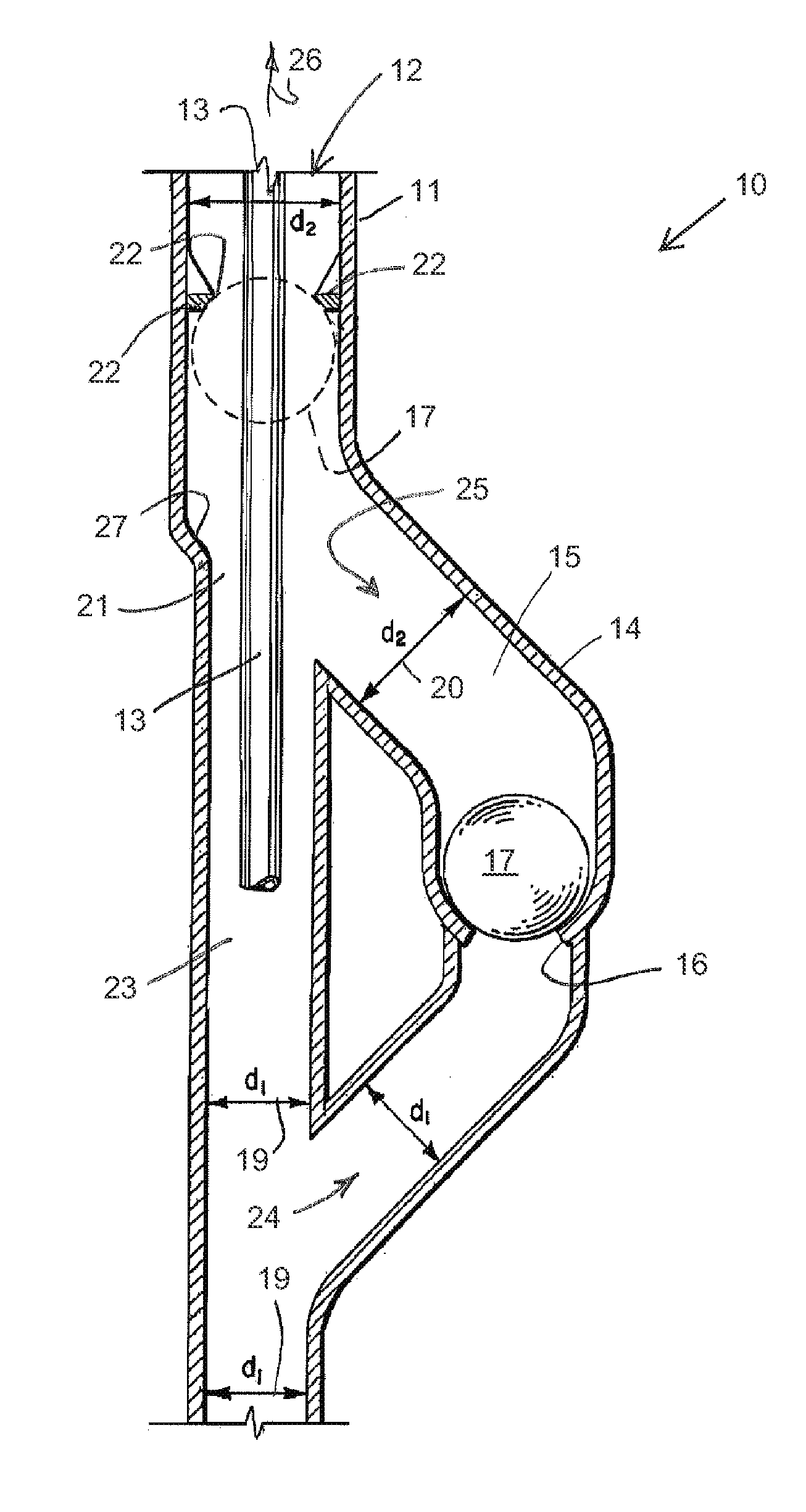
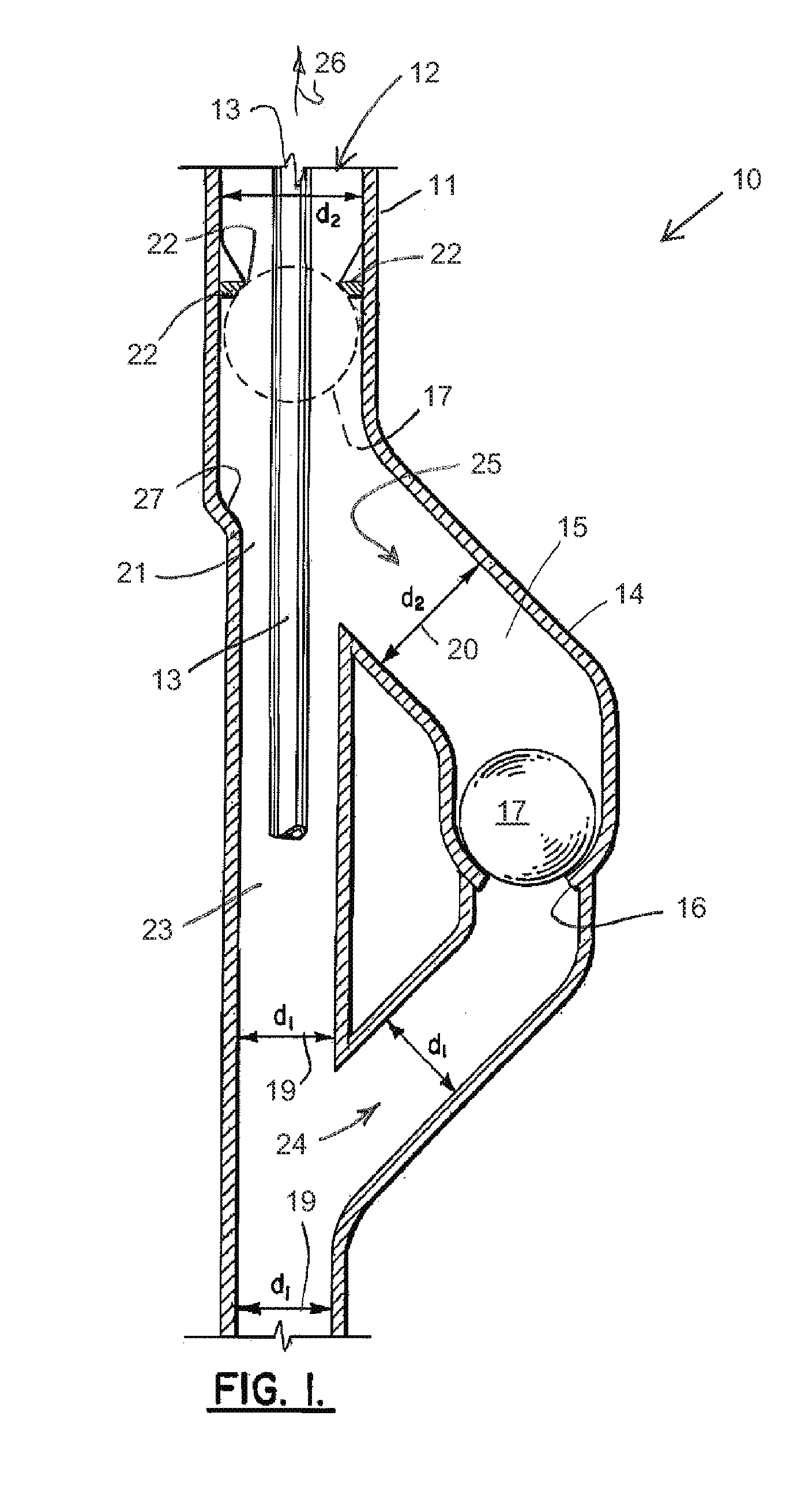
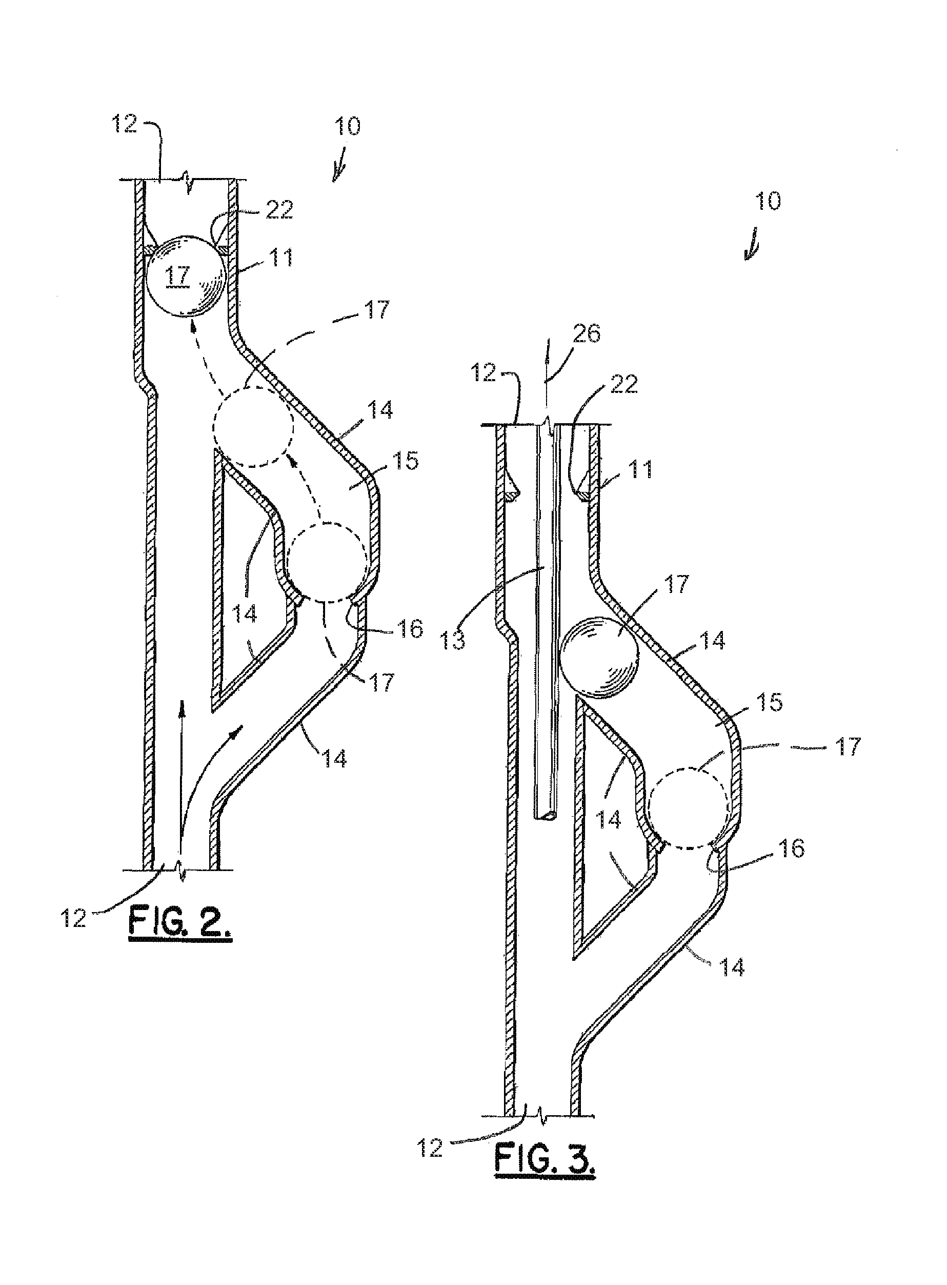
[0029]Oil well safety shut off apparatus is shown in FIGS. 1-7, designated generally by the numeral 10. Oil well safety shut off apparatus 10 can be used in a well casing 11 that surrounds a well bore 12 and blow out preventer (BOP) 18. In FIG. 7, a marine use is shown with drill ship 30, casing 11, blow out preventer 18 and seabed 31. Oil producing formation 32 is below seabed 31.

[0030]A drill string, work string or other string 13 extends downwardly into the well bore 12 and through the first bore 23 of the device 10. Circulating mud 21 can be located in first bore 23. First bore 23 has a diameter dl designated by the numeral 19. Diameter 19 of first bore 23 and the diameter of the well bore (i.e. casing 11 internal diameter) can be equal (see FIG. 7).

[0031]A branch flow line 14 has a bore 15 with a diameter (d2) designated by the numeral 20 and larger than the diameter designated by the numeral 19. The branch flow line 14 communicates with the first bore 23 at two spaced apart po...


PUM


Abstract

An oil well control device automatically shuts in a well responsive to the removal of a work string (or other removable structure—ball retarding structure) from the device. The device is placed in the well as a section of the well casing. The device provides a pair of bores, one that aligns with the well bore or well casing, the other being a branch flow line containing a ball structure that will close the well if the drill pipe or drill string is removed. While conducting normal well activity (e.g. drilling, work over or the like) the ball retarder (e.g. work string) prevents entry of the ball structure into the main flow channel.

Description

CROSS-REFERENCE TO RELATED APPLICATIONS[0001]This is a non provisional patent application of U.S. Provisional Patent Application Ser. No. 61 / 356,905, filed Jun. 21, 2010, and U.S. Provisional Patent Application Ser. No. 61 / 361,204, filed Jul. 2, 2010.[0002]Priority of U.S. Provisional Patent Application Ser. No. 61 / 356,905, filed Jun. 21, 2010, and U.S. Provisional Patent Application Ser. No. 61 / 361,204, filed Jul. 2, 2010, each of which is incorporated herein by reference, is hereby claimed.STATEMENT REGARDING FEDERALLY SPONSORED RESEARCH OR DEVELOPMENT[0003]Not applicableREFERENCE TO A “MICROFICHE APPENDIX”[0004]Not applicableBACKGROUND OF THE INVENTION[0005]1. Field of the Invention[0006]The present invention relates to an oil well safety device that automatically shuts in or closes an oil well if the drill string is removed or responsive to removal of the drill string to a position above the safety device.[0007]2. General Background of the Invention[0008]In the exploration of oi...

Claims


Application Information

Patent Timeline
Patent Type & Authority Applications(United States)
IPC IPC(8): E21B12/00E21B34/12
CPCE21B12/00E21B2034/002E21B34/12E21B34/08E21B2200/04
Inventor DAVIS, RAYMOND C.
Owner DAVIS RAYMOND C
Why Eureka
Try Eureka