Orthopedic implants and methods of manufacturing orthopedic implants

a technology of orthopaedic implants and manufacturing methods, which is applied in the direction of prosthesis, electron beam welding apparatus, arc welding apparatus, etc., can solve the problems of single type of orthopedic implants not being well suited for implantation into, different functions of different bones within the body, and different forces and stresses, so as to reduce the risk of infection, rapid prototyping, and rapid operation. the effect of speeding up the turnover time of the operating room

Active Publication Date: 2015-02-12
KAPSTONE MEDICAL LLC
View PDF5 Cites 59 Cited by
  • Summary
  • Abstract
  • Description
  • Claims
  • Application Information

AI Technical Summary

Benefits of technology

[0008]In accordance with another preferred embodiment, the present invention provides various embodiments of a foot and ankle porous orthopaedic implant device utilizing specialized CAD software to selectively adjust and optimize properties of porous and solid structures and fabricated using e.g., Direct Metal Laser Sintering (DMLS) or Electron Beam Melting (EBM) method using a variety of materials including, but not limited to, titanium (CP and alloy), cobalt chrome, stainless steel, magnesium, niobium, and tantalum. These devices are used for correcting various foot and ankle deformities, disorders, and trauma for both adult as well as pediatric patients. Where applicable, the devices are anatomically shaped and sized, in part, based on sawbone models (such as that available from Pacific Research). A porous band is provided around the periphery of the implants to promote involucrum. Solid portion(s) are provided for strength of clinical loading patterns. Holed and non-holed implant design options are available. The holed option provides for a variety of biologics (ie: allograft, autograft, etc) and / or ancillary fixation (screws, pins, etc). Various angle wedges, multiple thickness blocks, and several rod diameters are provided to meet the clinical needs. The advantages of these devices over the traditional bone sources (allograft, autograft) for correction include, but are not limited to: Pre-sized for optimal fit, Reliable and consistent strength, and Increased safety / lower risk of infection.
[0011]To take advantage of these selectively adjusted and optimized porous properties provided by the CAD software, the preferred commercially available manufacturing method is to utilize Direct Metal Laser Sintering, or DMLS, as it has been optimized for this computer program. DMLS allows the device to be fabricated in such a manner as to alternate from a porous structure to a solid structure as it is built layer by layer. One such manufacturing system that is compatible with the described CAD software is provided by Electro Optical Systems (EOS). Additionally, EBM is an alternate manufacturing method provided by Arcam. Another advantage of using this system is the cost savings over specialized and conventional manufacturing methods, as it is less affected by set-up costs, economies of scale, and requires minimal steps to fabricate the device.
[0013]Where applicable, the devices utilize general surgical instrumentation readily available in an orthopaedic operating room. Where applicable however, provisionals (trial devices) and other device specific surgical instruments can be provided as a single-use, sterile kit to minimize the risk of infection from improper sterilization of reusable instrumentation. Furthermore, these instruments can also be manufactured in a rapid prototyping fashion. Also, these kits will provide for a quicker operating room turnover time, as the surgical tools do not have to be cleaned and re-sterilized.

Problems solved by technology

However, different bones within the body have different functions and as such are exposed to different forces and stresses.
Consequently, a single type of orthopedic implant is not well suited for implantation into the various types of bones which experience different forces and stresses.

Method used


Image

  • Orthopedic implants and methods of manufacturing orthopedic implants
  • Orthopedic implants and methods of manufacturing orthopedic implants
  • Orthopedic implants and methods of manufacturing orthopedic implants

Examples


Embodiment Construction

[0053]Reference will now be made in detail to the preferred embodiments of the invention illustrated in the accompanying drawings. Wherever possible, the same or like reference numbers will be used throughout the drawings to refer to the same or like features. It should be noted that the drawings are in simplified form and are not drawn to precise scale. In reference to the disclosure herein, for purposes of convenience and clarity only, directional terms such as top, bottom, front, rear, side, above, below and diagonal, are used with respect to the accompanying drawings. Such directional terms used in conjunction with the following description of the drawings should not be construed to limit the scope of the invention in any manner not explicitly set forth. Additionally, the term “a,” as used in the specification, means “at least one.” The terminology includes the words above specifically mentioned, derivatives thereof, and words of similar import.

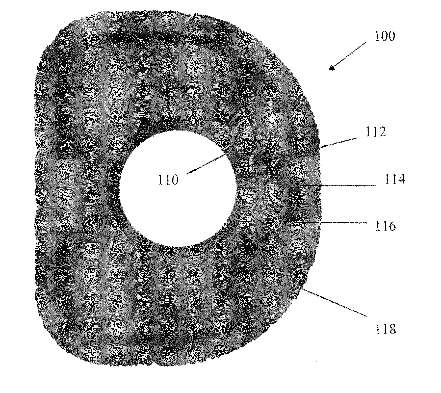
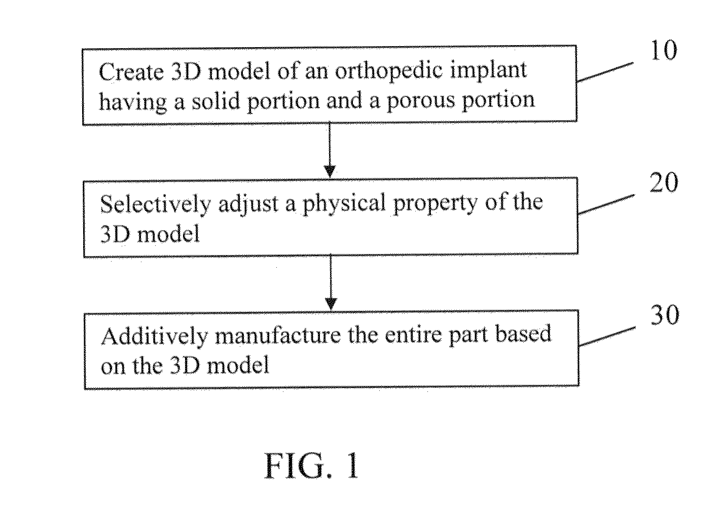
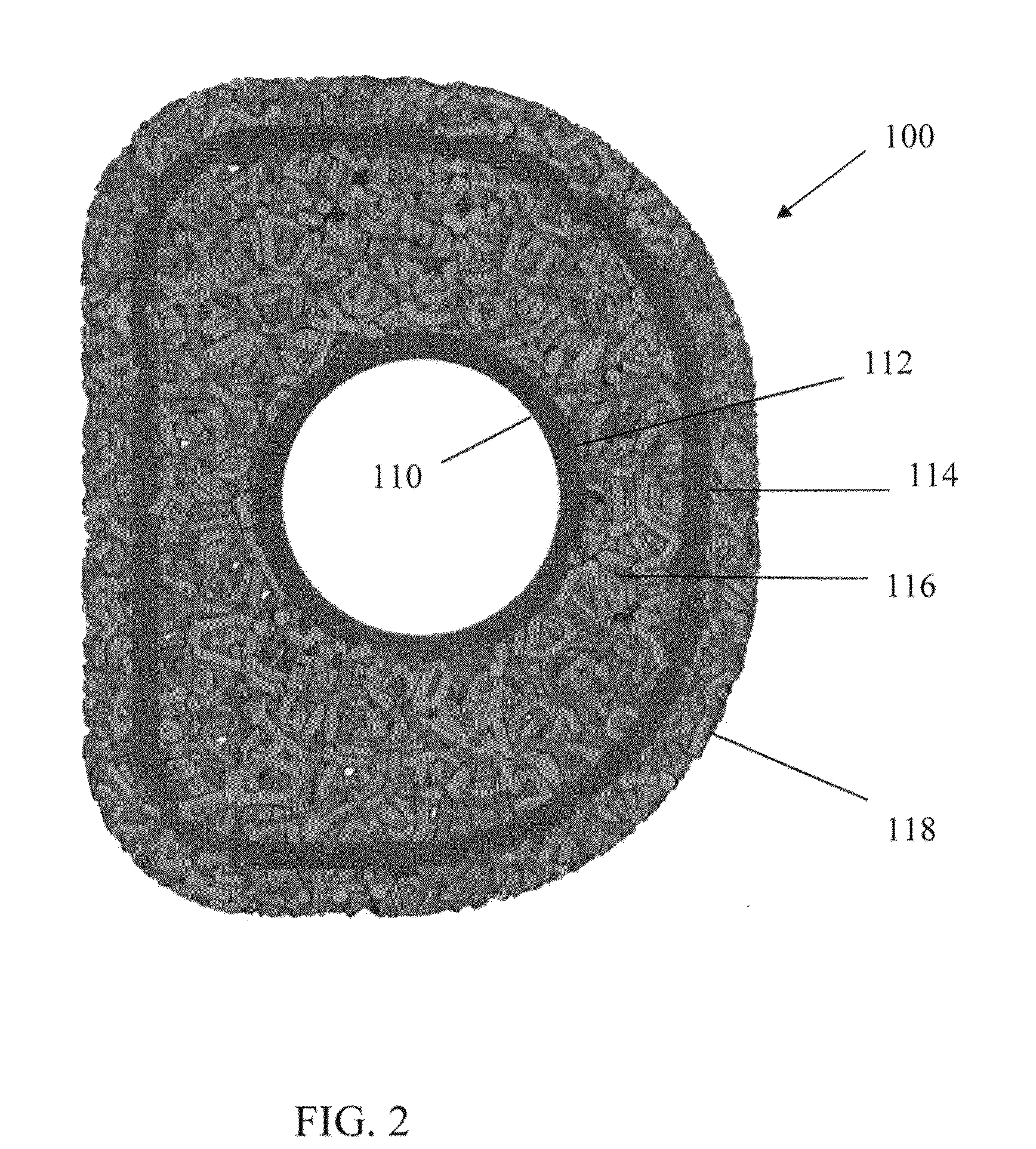
[0054]Referring to FIG. 1, there i...


PUM

PropertyMeasurementUnit
pore diameteraaaaaaaaaa
diameteraaaaaaaaaa

Abstract

A method of manufacturing an orthopedic implant is provided. The method includes creating a 3D model of an orthopedic implant having a solid portion and a porous portion and selectively adjusting a physical property of at least one of porosity of the porous portion, lattice thickness of the porous portion, beam profile of the porous portion, and topography of the 3D model. The entire implant is then additively manufactured based on the 3D model.

Description

CROSS-REFERENCE TO RELATED APPLICATIONS [0001]This application claims the benefit of U.S. Provisional Application No. 61 / 964,091, filed Aug. 9, 2013, the entire disclosure of which is incorporated by reference herein in its entirety.BACKGROUND OF THE INVENTION [0002]The present invention relates generally to orthopedic implants and methods of manufacturing an orthopedic implant. In particular, the present invention relates to an orthopedic implant having a porous portion and a solid portion manufactured by an additive manufacturing process.[0003]In the realm of orthopedic surgery, it is known to use implants to fix the position of bones. In this way, bones can be reconstructed, and malformations or other injuries corrected. However, different bones within the body have different functions and as such are exposed to different forces and stresses. Consequently, a single type of orthopedic implant is not well suited for implantation into the various types of bones which experience diff...

Claims


Application Information

Patent Timeline
Patent Type & Authority Applications(United States)
IPC IPC(8): A61F2/42B22F3/105B22F7/00B23K15/00
CPCA61F2/4202B22F2202/11B23K15/0086B22F3/1055B22F7/004A61F2002/4207A61F2002/30187A61F2002/30118A61F2002/30133A61F2002/30156A61F2002/30153A61F2002/30158A61F2002/30131A61F2002/30224A61F2310/00011B23K15/0006A61F2/3094A61F2002/30011A61F2002/30962A61F2002/3097A61F2002/4223B23K26/0006B23K26/32B23K26/342B22F5/106B22F7/06B23K26/354B23K2103/05B23K2103/08B23K2103/14B23K2103/15B23K2103/26B23K2103/50Y02P10/25B22F10/28B22F10/38
Inventor NEAL, DAVID J.
Owner KAPSTONE MEDICAL LLC
Why Eureka
Try Eureka