
Video transceiver system, video transmission method, and transmission device

Inactive Publication Date: 2015-02-12
MITSUBISHI ELECTRIC CORP
View PDF4 Cites 1 Cited by
  • Summary
  • Abstract
  • Description
  • Claims
  • Application Information

AI Technical Summary

Benefits of technology

The patent aims to prevent video quality from decreasing.

Problems solved by technology

When communicating via a transponder such as satellite communications and satellite broadcasting, non-linear characteristics of an amplifier and a transponder cause waveform distortion, which has a negative influence on transmission performance.
Furthermore, in a Line of Sight (LOS) communication that does not use a transponder, non-linear characteristics of an amplifier cause waveform distortion, which has a negative influence on transmission performance.

Method used


Image

  • Video transceiver system, video transmission method, and transmission device
  • Video transceiver system, video transmission method, and transmission device
  • Video transceiver system, video transmission method, and transmission device

Examples


Embodiment Construction

[0018]An embodiment of the present disclosure will be described, in detail, hereafter with reference to the drawings.

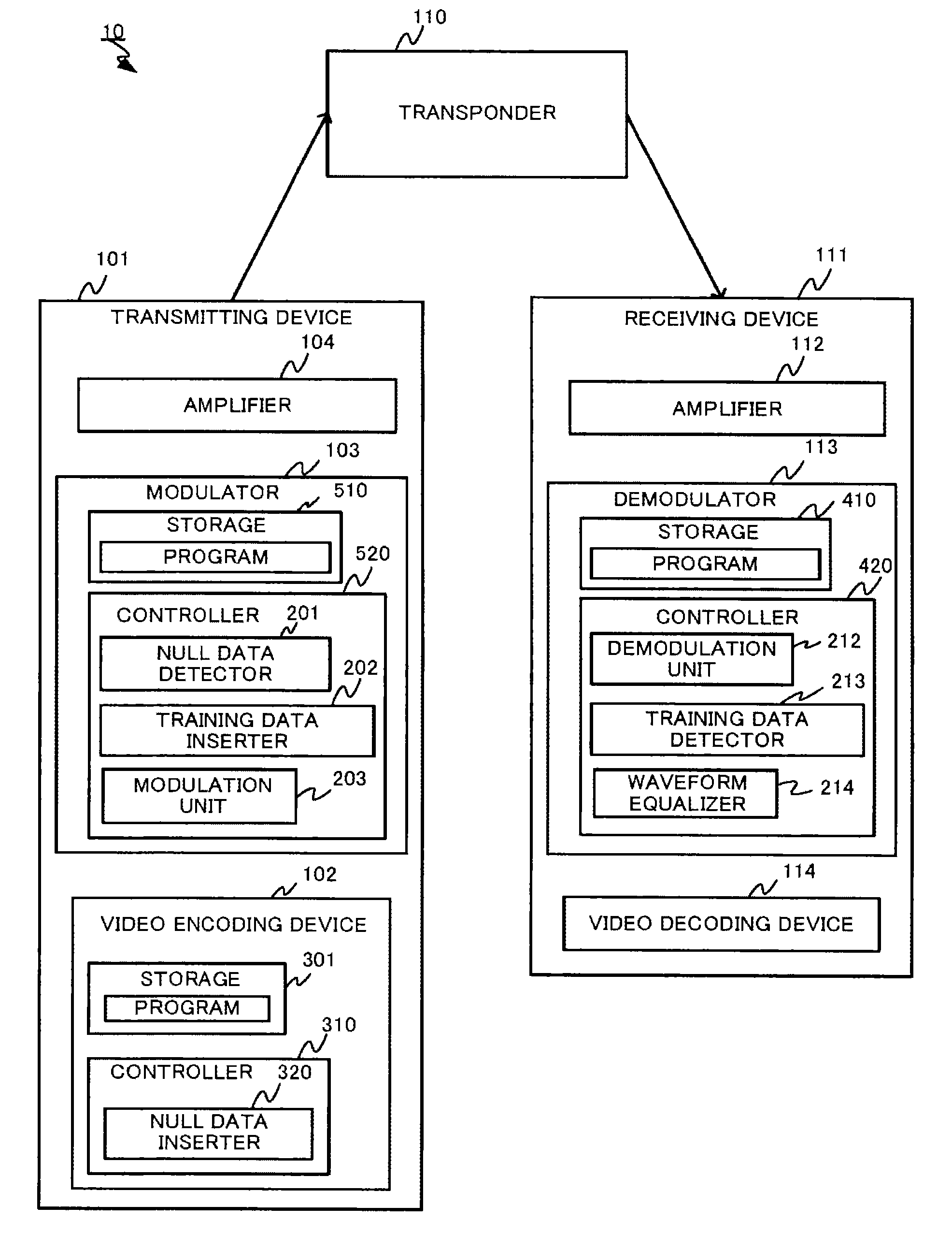
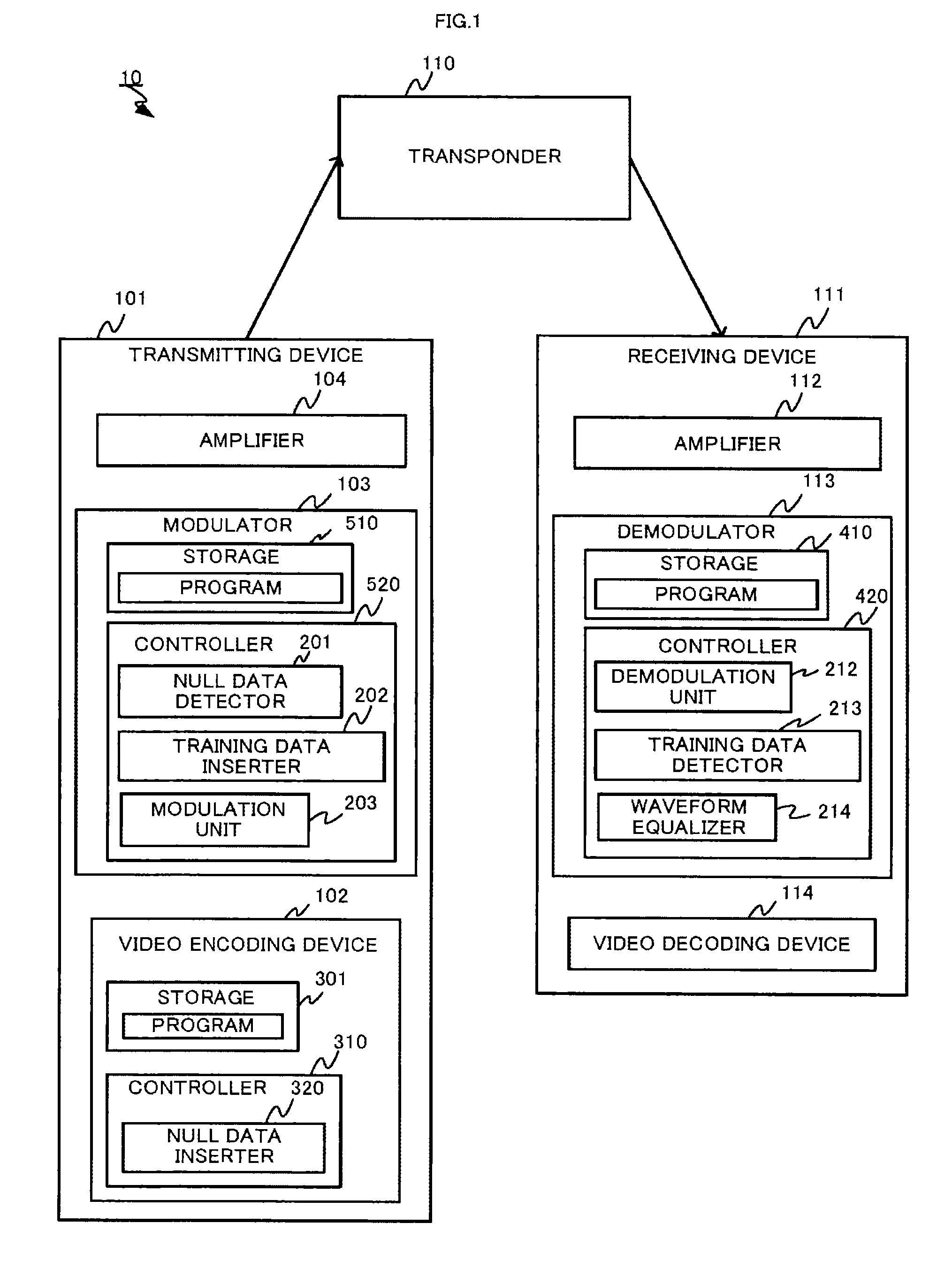
[0019]A video transmitting and receiving system 10 includes, as shown in FIG. 1, a transmitting device 101, a transponder 110, and a receiving device 111. A signal transmitted from the transmitting device 101 is propagated to the receiving device 111 via the transponder 110.

[0020]The transmitting device 101 is a device that performs processes of encoding, modulation, amplification and the like of the input video signal, and transmits a video encoded signal processed by the above-mentioned processes to the transponder 110. The transmitting device 101 is configured to have a video encoding device 102, a modulator 103, an amplifier 104 and the like.

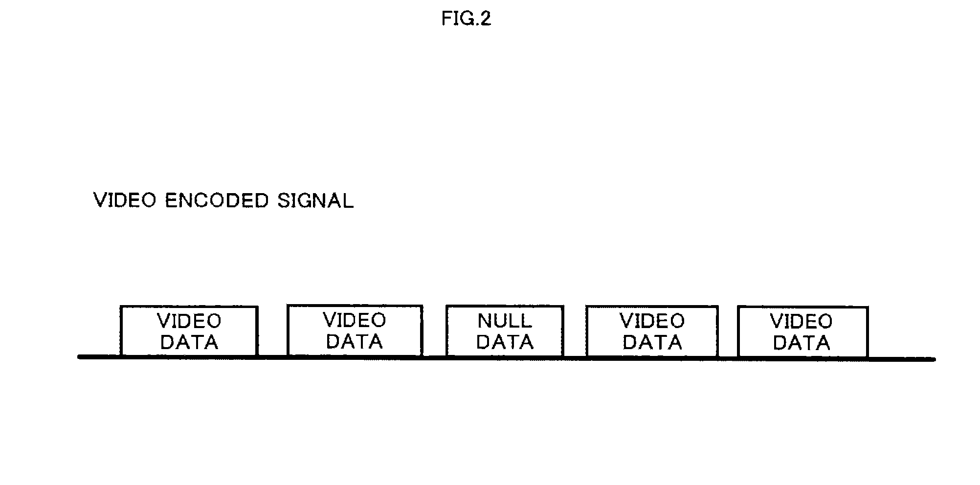
[0021]The video encoding device 102 is such a device that generates, by encoding the input video signal, the video encoded signal as shown in FIG. 2, and supplies the video encoded signal to the modulator 103. The video encodi...


PUM


Abstract

A video transmitting and receiving system includes a transmitting device that transmits a packet, and a receiving device that receives the packet transmitted from the transmitting device. The transmitting device inserts null data into an unused space after a video signal has been encoded and generates a packet having a predetermined packet length. Then, the null data is replaced with known data to modulate and the packet is transmitted. The receiving device receives the transmitted packet to demodulate and waveform distortion of the packet is detected based on the known data pre-registered to correct so as to perform waveform equalization.

Description

TECHNICAL FIELD[0001]The present disclosure relates to a video transmitting and receiving system, video transmitting method and transmitting device.BACKGROUND ART[0002]When communicating via a transponder such as satellite communications and satellite broadcasting, non-linear characteristics of an amplifier and a transponder cause waveform distortion, which has a negative influence on transmission performance. Furthermore, in a Line of Sight (LOS) communication that does not use a transponder, non-linear characteristics of an amplifier cause waveform distortion, which has a negative influence on transmission performance.[0003]There are various proposals against performance degradation, such as, by comparing a waveform of known data within transmission data series with a waveform of known data received at a reception side, the component of the waveform distortion generated between the transmission and reception is detected and is removed by an inverse correction.[0004]For example, Pa...

Claims


Application Information

Patent Timeline
IPC IPC(8): H04N21/236H04N21/438
CPCH04N21/236H04N21/4382H04N21/23611H04N21/23614H04N21/2383
Inventor YOSHIOKA, MASARUYAMAMOTO, YOSHIHIKO
Owner MITSUBISHI ELECTRIC CORP
Learn More