
Goggle type display device, eye gaze detection method, and eye gaze detection system

Active Publication Date: 2019-03-14
LAPIS SEMICON CO LTD
View PDF34 Cites 6 Cited by
  • Summary
  • Abstract
  • Description
  • Claims
  • Application Information

AI Technical Summary

Benefits of technology

The present invention is aimed at providing a goggle type display device, an eye gaze detection method, and an eye gaze detection system that can detect the eye gaze position of a user without compromising image quality or adding significantly to the cost or size of the device. The technical effects of this invention include improved user experience, reduced cost and size of the display device, and improved detection of eye gaze position.

Problems solved by technology

In the aforementioned head-mounted display using the half mirror, since the half mirror is disposed between the eye and a screen, the image quality of the display may deteriorate.
Moreover, the cost of such a head-mounted display increases by an amount corresponding to the cost of the half mirror, and the size of a VR case (goggles) increases by the addition of the half mirror.
The employment of the wide-angle lens or the large number of cameras leads to a cost increase corresponding to such a wide-angle lens or the number of cameras.

Method used


Image

  • Goggle type display device, eye gaze detection method, and eye gaze detection system
  • Goggle type display device, eye gaze detection method, and eye gaze detection system
  • Goggle type display device, eye gaze detection method, and eye gaze detection system

Examples


first embodiment

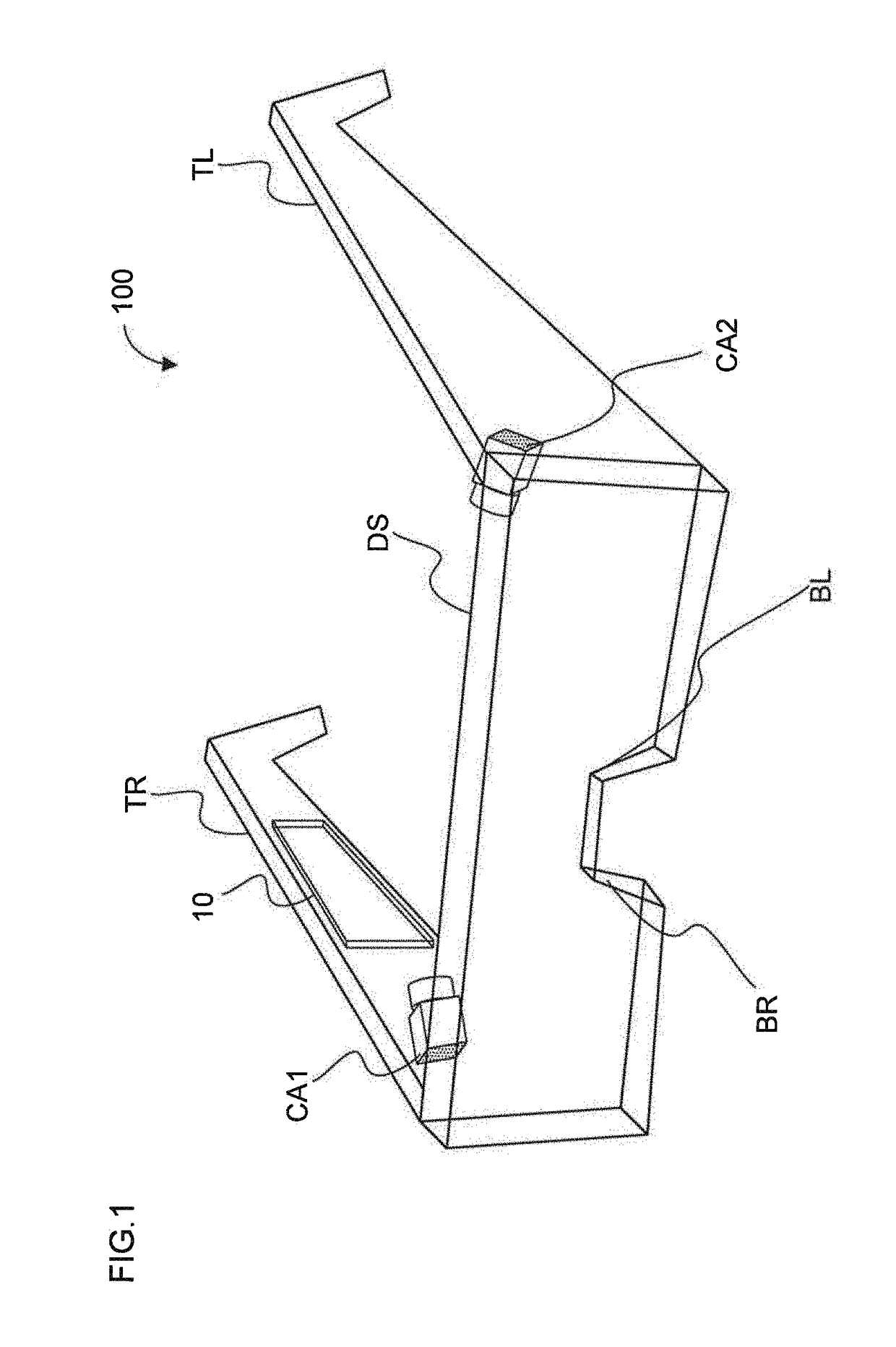
[0025]FIG. 1 is a schematic diagram showing an appearance of a goggle type display device 100 according to the present embodiment. An example of the goggle type display device 100 is a pair of virtual reality (VR) goggles used for displaying VR video. The goggle type display device 100 is constituted by a goggle-shaped frame that can be worn on the head of a user.

[0026]The goggle-shaped frame has left and right temples TL and TR, which are parts to be hooked on the ears of the user when worn. The goggle-shaped frame is worn on the head of the user with left and right parts (indicated as BL and BR in the figure) of a bridge having been in close contact with the ridge of the nose. A display (screen DS) is provided between the left and right temples TL and TR and in front of the eyes of the user wearing the goggle-shaped frame.

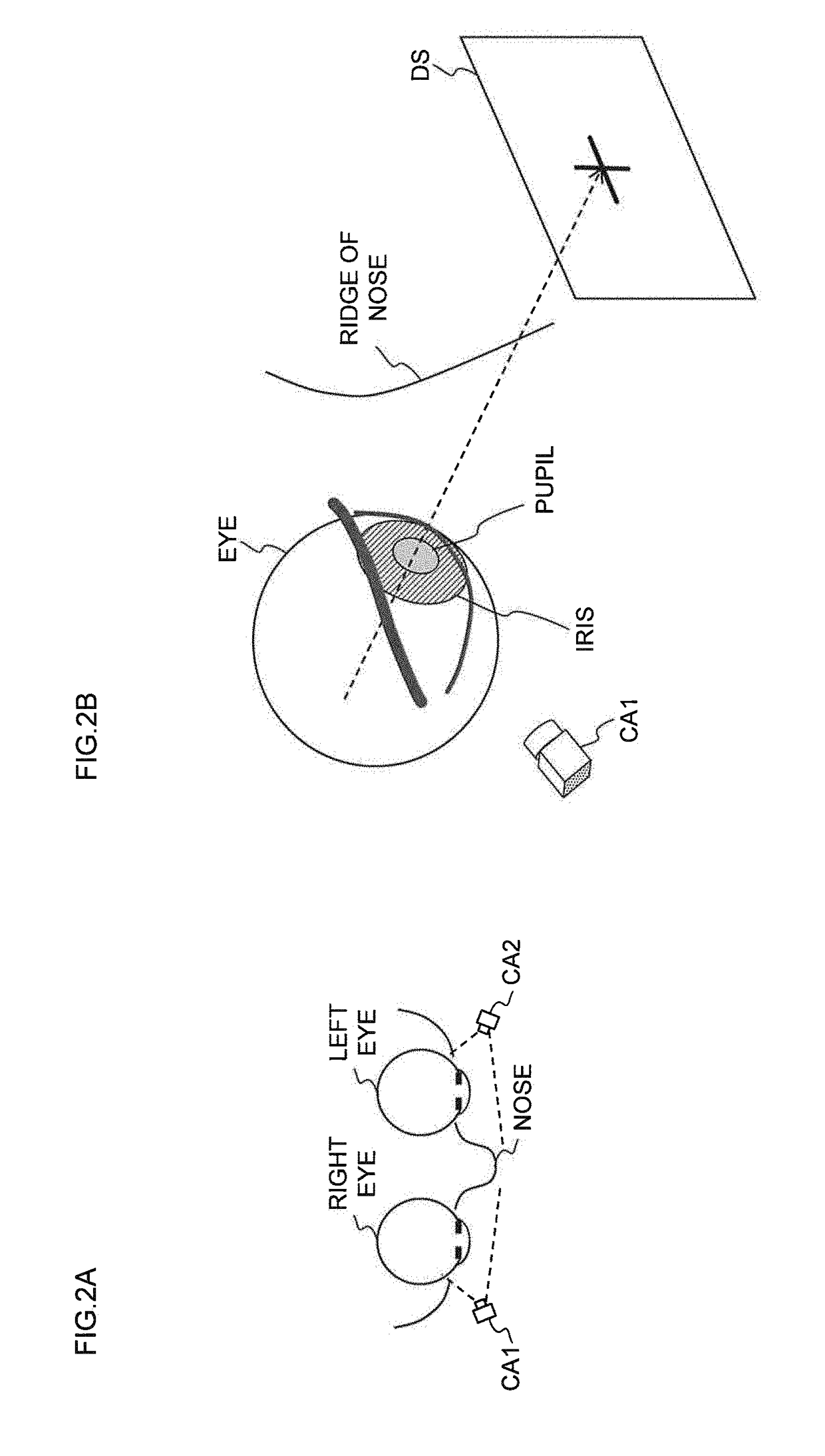
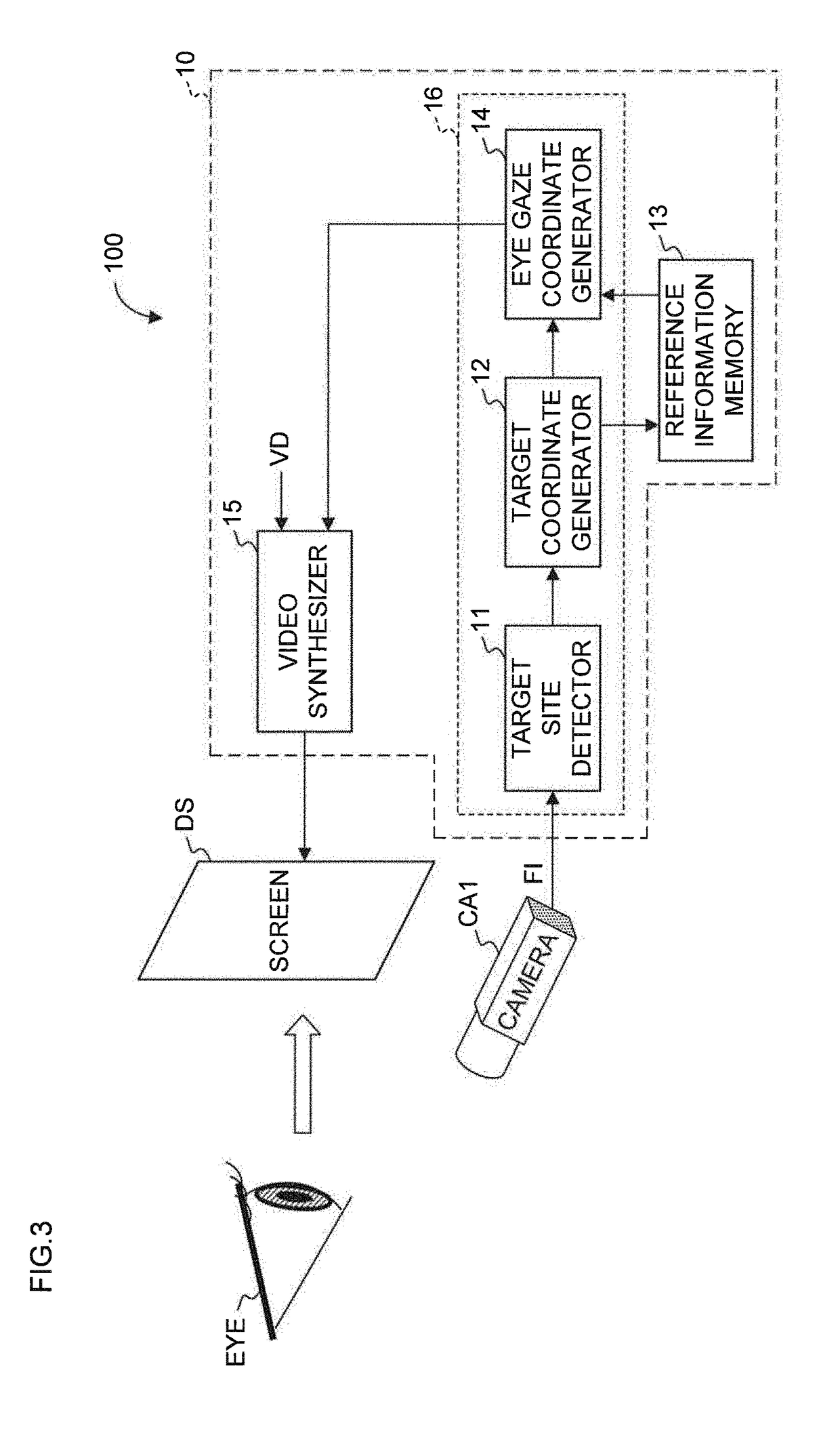
[0027]Cameras CA1 and CA2 are mounted inside of the goggle-shaped frame. The camera CA1 is disposed at a position closer to the screen DS on an inner side surfac...

second embodiment

[0055]A goggle type display device of the present embodiment differs from the goggle type display device 100 of the first embodiment in that a camera CA3 that photographs the right eye from the left side of the right eye and a camera CA4 that photographs the left eye from the right side of the left eye are provided in addition to the cameras CA1 and CA2. The camera CA3 is disposed, for example, in the right part BR of the bridge shown in FIG. 1. The camera CA4 is disposed, for example, in the left part BL of the bridge shown in FIG. 1.

[0056]FIG. 6 is a schematic diagram showing a positional relationship between the cameras in the goggle type display device of the present embodiment and the eyes and nose of the user as viewed from above in a direction from the top of the head of the user toward the toes. As with the first embodiment, the camera CA1 photographs the right eye and the ridge of the nose of the user from the right side. The camera CA2 photographs the left eye and the ridg...


PUM


Abstract

A goggle type display device with a goggle-shaped frame and a display mounted on said frame includes: an image-capturing unit disposed inside of the frame; and an eye gaze position estimator that estimates an eye gaze position on the basis of images of an eye and a ridge of a nose included in a facial image captured by said image-capturing unit.

Description

BACKGROUND OF THE INVENTION1. Field of the Invention[0001]The present invention relates to a goggle type display device, an eye gaze detection method, and an eye gaze detection system.2. Description of the Related Art[0002]Video display devices that display 3D video (images) on head-mounted displays have been known with the advent of techniques such as virtual reality (VR) or augmented reality (AR). With such a video display device, which position in a displayed image a user is looking at (hereinafter referred to as an eye gaze position of the user) is detected, and the detected eye gaze position of the user is displayed with a “+” mark, for example, being superimposed on the displayed image.[0003]The eye gaze position of the user is detected by shooting an eye of the user by a camera and estimating the eye gaze position on the basis of the video of the eye such as a movement of the retina or the iris. For example, a face detection method in which a pupil image is obtained by a came...

Claims


Application Information

Patent Timeline
IPC IPC(8): H04N13/383H04N13/332H04N5/225G06K9/00
CPCH04N13/383H04N13/332H04N5/2253G06K9/00604G06K9/00248A61F9/06G06V40/193G06V40/19H04N23/57G06F3/013G06V40/165H04N23/54
Inventor AKAHORI, HIROJI
Owner LAPIS SEMICON CO LTD
Learn More