Propulsor arrangement for a marine vessel and a marine vessel constructed with this type of propulsor arrangement

a propulsor and marine technology, which is applied in the field of propulsor arrangement for marine vessels and marine vessels constructed with this type of propulsor arrangement, can solve the problems of limited power, limited size of azimuthing propulsor, and limit the availability of large ice-heavy azimuthing propulsors, so as to reduce the stress on the propeller and reduce the stress on the unit structure. , the effect of less interaction

Active Publication Date: 2015-02-19
KONGSBERG MARITIME SWEDEN AB
View PDF3 Cites 7 Cited by
  • Summary
  • Abstract
  • Description
  • Claims
  • Application Information

AI Technical Summary

Benefits of technology

[0010]With this invention the power can be increased so that larger vessels can be used without increasing the physical size of the propulsors, which would otherwise require an increased draft of the vessel. This invention will also increase redundancy and operational flexibility which will improve performance and safety of the vessel in various modes of operation.
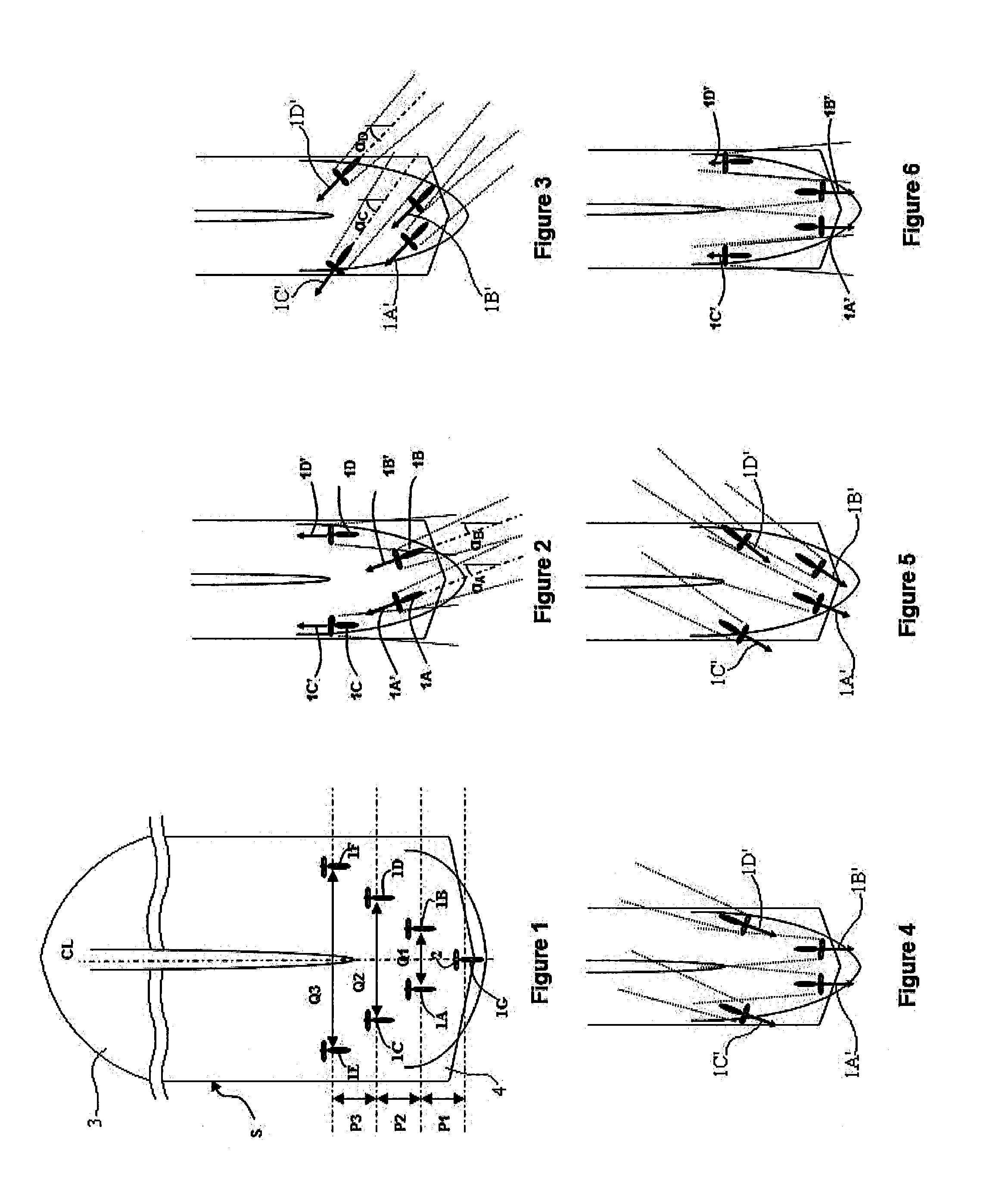
[0013]According to one preferable design aspect for an arrangement according to the invention, using multiple propulsors, situations may be avoided when the slipstream from one propulsor hits another one, without reducing the main operational performances of the vessel.
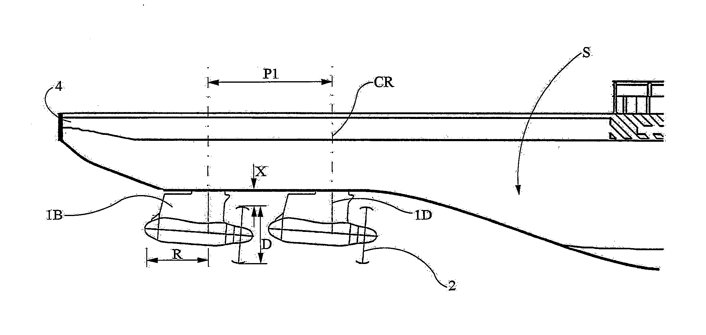
[0015]Preferably four azimuthing propulsors are used, but could also be more or less, for example 3, or 5 to 7. One benefit of using multiple propulsors instead of a few is that the same total propeller disc area can be achieved by using a smaller propeller diameter. This is beneficial in ice operation in that the distance between the tip of the propeller and the hull, i.e. the propeller tip clearance can be kept bigger, assuming a specified draft of the vessel. This is beneficial in that it allows for less interaction with level ice and thus less stress to the propellers. This could alternatively be used in that the strut of the propulsor can be kept shorter to achieve less stress to the unit structure, by having less leverage of the ice loads acting on the propeller and structure. This also facilitate design of vessels for shallow draft and can keep the ballast draft low also for bigger vessels, thus reducing fuel consumption during the ballast voyage, without cargo.
[0016]This invention gives significant advantages to the design of vessels that is intended to operate in open as well as icy waters, for instance an icebreaker or a tanker, a cargo or a container vessel or similar transport vessel. It is possible to use larger vessels, which is important for the economy of most transportation project, without giving up requirement on maneuvering and icebreaking capability in shallow waters. In fact this invention will, as described in the following detailed description and in the claims, give an increased operational flexibility of the vessels which can be used to improve the icebreaking performance for the DAS concept. The invention will also increase the redundancy for propulsion and steering of the vessel, thus increasing significantly the safety of operation.

Problems solved by technology

The disadvantage of these configurations is that the available power is limited due to the limitation in size of azimuthing propulsors.
The size of the azimuthing propulsor is limited by the possibility to fit it under the hull due to its physical size and weight.
There are also design limitations that limits the availability of large ice strengthened azimuthing propulsors.
The requirements defined by classification societies for vessels operating in ice will also put limitations on the available sizes.
This solution has significant disadvantages in that the power available for steering is significantly reduced, as the centre propeller which is designed to take a large part of the power is fixed and can only deliver thrust in astern direction to push the vessel ahead and to a limited extent in the opposite direction when it is reversed.
Furthermore, the centre propeller tends to be large in diameter when high thrust is needed, thus increasing the draft of the vessel and the required ballast draft and thereby increasing fuel consumption during the ballast voyage.
US20050070179 in a speculative manner mention that a POD may be used in place of the center propeller, however such an arrangement does also present disadvantages due to the positioning of the POD in the center.
The disadvantage of less maneuvering capability becomes more significant when operating in ice, and the turning radius for a long vessel could become larger than what is acceptable, thus reducing the possible size of the vessel.
A big propeller in the centre will also move the two azimuthing propulsors apart a distance, to avoid the slipstream from the centre propeller when moving ahead in forward direction, thus increasing the risk that big ice blocks can accumulate and get stuck in the centre when moving ahead in aftward direction during icebreaking.
Moreover from U.S. Pat. No. 6,439,936B1 there is known a drill ship which uses a plurality of propulsor units, which arrangement seen from a ice breaking perspective presents disadvantages from several aspect, e.g. by using several centrally positioned POD units.

Method used


Image

  • Propulsor arrangement for a marine vessel and a marine vessel constructed with this type of propulsor arrangement
  • Propulsor arrangement for a marine vessel and a marine vessel constructed with this type of propulsor arrangement
  • Propulsor arrangement for a marine vessel and a marine vessel constructed with this type of propulsor arrangement

Examples


example 1

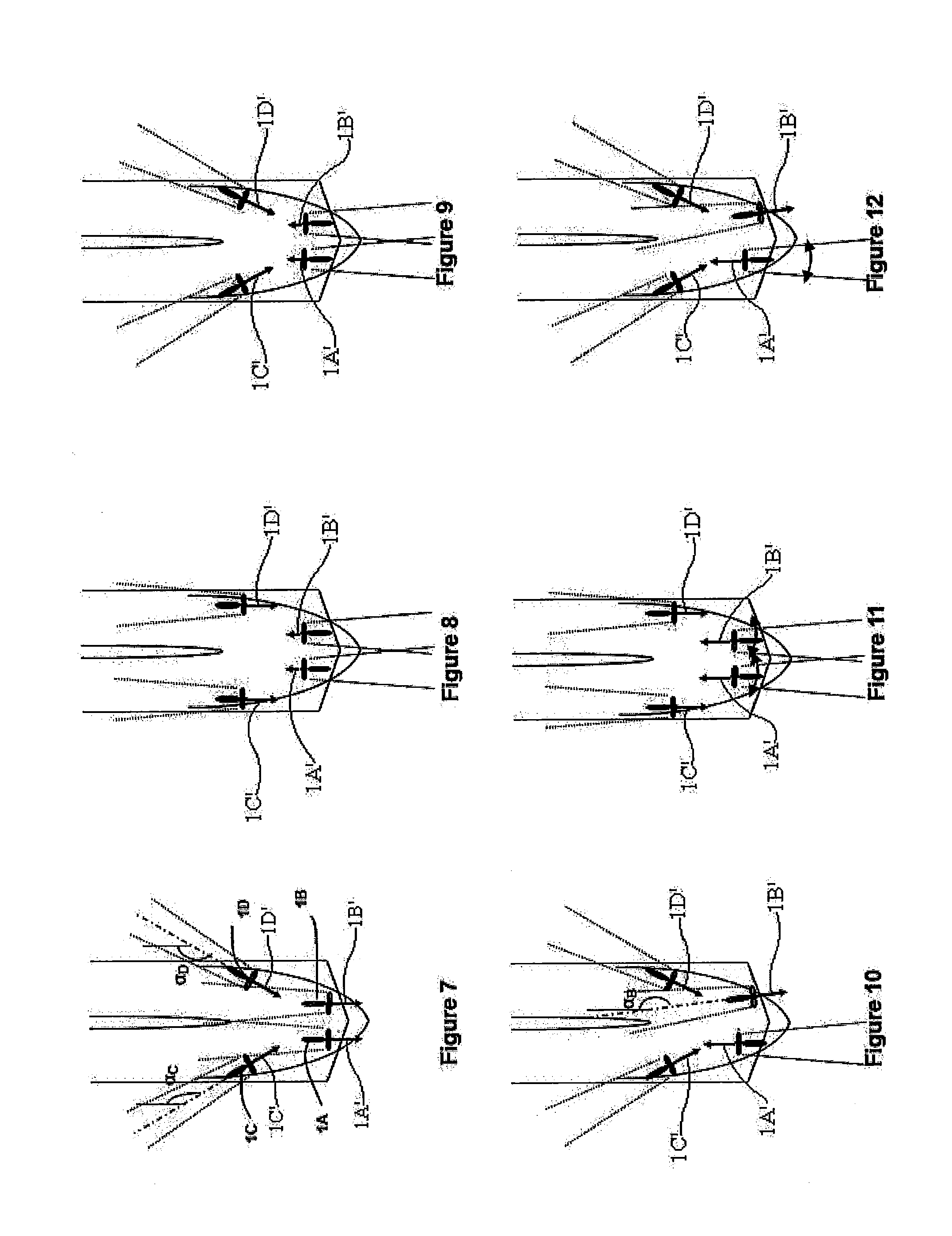
[0059]When operating in heavy ice with a single or twin propulsor arrangement, especially during ice milling with a DAS, there is a risk that the propellers get stuck in the ice. To break loose from such a situation it is required that the propulsors are heavily over-dimensioned with regard to available shaft torque and / or azimuthing torque. In a multiple propulsor arrangement the risk that all propulsors should get stuck at the same time is negligible, so in case the aftmost propulsor(s) get stuck the others can be used to pull the vessel in direction from the ice so as to release the aftmost propulsors from the ice.

[0060]When using the aftmost propulsors to penetrate a ridge it is possible to balance the astern thrust with the forward propulsors to reduce the risk for the propellers to get stuck and to optimize the penetration speed. In FIG. 6 is shown a situation where the aftmost propulsors are used to penetrate an ice formation while the foremost propulsors are used to control ...

example 2

[0061]It is known that certain types of gas engines, used to motor generators to produce electricity onboard a vessel, are sensitive to load fluctuations, such that if the propeller looses its rpm, while penetrating an ice formation, the power consumption will be reduced very quickly and there is a risk that it could create a blackout onboard. With a multiple configuration of propulsors the load fluctuation, when a propulsor looses its rpm will be smaller as the power on each propulsor is smaller. However it can be further reduced if operating as in FIG. 6. If the rpm on the forward Pod drives is increased when the rpm on the aftmost is reduced, the power fluctuation on the system will also be reduced. This way of controlling the propulsors will have the dual effect of releasing the aftmost propulsors so that they can more quickly restore their rpm.

[0062]It is evident that for the skilled person that the specific method described in the two paragraphs above is not limited to use in ...

example 3

[0063]In FIG. 7 the foremost Pod drives, 1C and 1D, have been turned inwards with angles αc and αD, to transport the ice milled by the aftmost Pod drives 1A and 1B, away from the vessels hull and reduce the friction, without operating in the direct slipstream of the aftmost Pod drives. The reduced friction between the ice and the hull means reduced power to move the vessel. The water wash from the foremost Pod drives, which is directed to the sides of the broken channel, will break the ice on the sides and thus assist to widen the channel. This way of operation can also be used to clean a channel from brash ice, as the forward Pod drives can push the broken ice outwards and below the remaining ice field.


PUM


Abstract

A propulsor arrangement for operation in icy as well as open water, for a marine vessel having a hull (S) with a center line (CL) extending between a forward end (3) and an aft end (4), said propulsor arrangement comprising a plurality of azimuthing thrusters (1A-ID) having a centre of rotation (CR) and a longest lateral distance (R) that it protrudes from said centre of rotation (CR), preferably having at least one azimuthing thruster (1A-ID) with a propeller (2) arranged to act in ice, wherein said propulsor arrangement includes at least three azimuthing thrusters (1A, 1B, 1G) positioned close to one end (3, 4) of said hull (S), including at least one pair (1A, 1B) positioned substantially symmetrical in relation to said center line (CL) along a transversal line in relation to said center line (CL) a first distance (Q1) apart a and at least one azimuthing thruster (1G) positioned closer to said end (3, 4) and said centerline (CL) and positioned a longitudinal distance (P1) away from said transversal line.

Description

FIELD OF THE INVENTION[0001]The present invention relates to a propulsor arrangement, to steer and propel a marine vessel in forward or aftward direction that is intended to operate in open as well as icy waters, for instance an icebreaker or a tanker, a cargo or a container vessel or similar transport vessel, comprising a plurality of azimuthing propulsors. The invention also relates to a marine vessel intended to operate in open as well as icy waters having such a propulsor arrangement.BACKGROUND OF THE INVENTION[0002]Some marine vessels use a kind of propulsor that has a steering arrangement such that the propeller and its thrust can be directed in different directions. Such azimuthing propulsors can therefore be used for both steering and propulsion and therefore eliminates the need of rudders and stern tunnel thrusters, in addition such azimuthing propulsors have proven to be efficient in connection with icebreaking. The azimuthing propulsors comprises a casing with a strut and...

Claims


Application Information

Patent Timeline
Patent Type & Authority Applications(United States)
IPC IPC(8): B63H5/125B63H25/42B63B35/08
CPCB63H5/125B63H25/42B63B35/08B63H2005/1254B63H5/1252
Inventor HENRIKSEN, THOMAS
Owner KONGSBERG MARITIME SWEDEN AB
Why Eureka
Try Eureka