Encapsulated magnetron

a magnetron and encapsulation technology, applied in the field of magnets, can solve the problems of hardware handling problems, lessen the useful life of the magnetron and the target,

Active Publication Date: 2015-02-19
APPLIED MATERIALS INC
View PDF5 Cites 8 Cited by
  • Summary
  • Abstract
  • Description
  • Claims
  • Application Information

AI Technical Summary

Problems solved by technology

If the magnetron and/or the target are heated above a designated process temperature, then the high temperature may after the performance of the process by changing the sputtering rate or sputtering uniformity on the target and lessening the useful lives of

Method used


Image

  • Encapsulated magnetron
  • Encapsulated magnetron
  • Encapsulated magnetron

Examples


Embodiment Construction

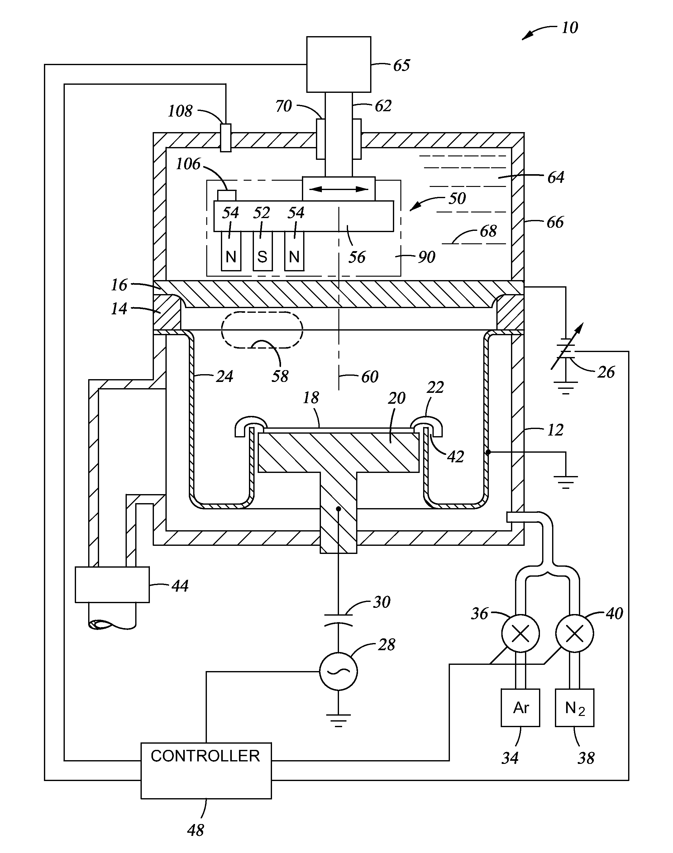
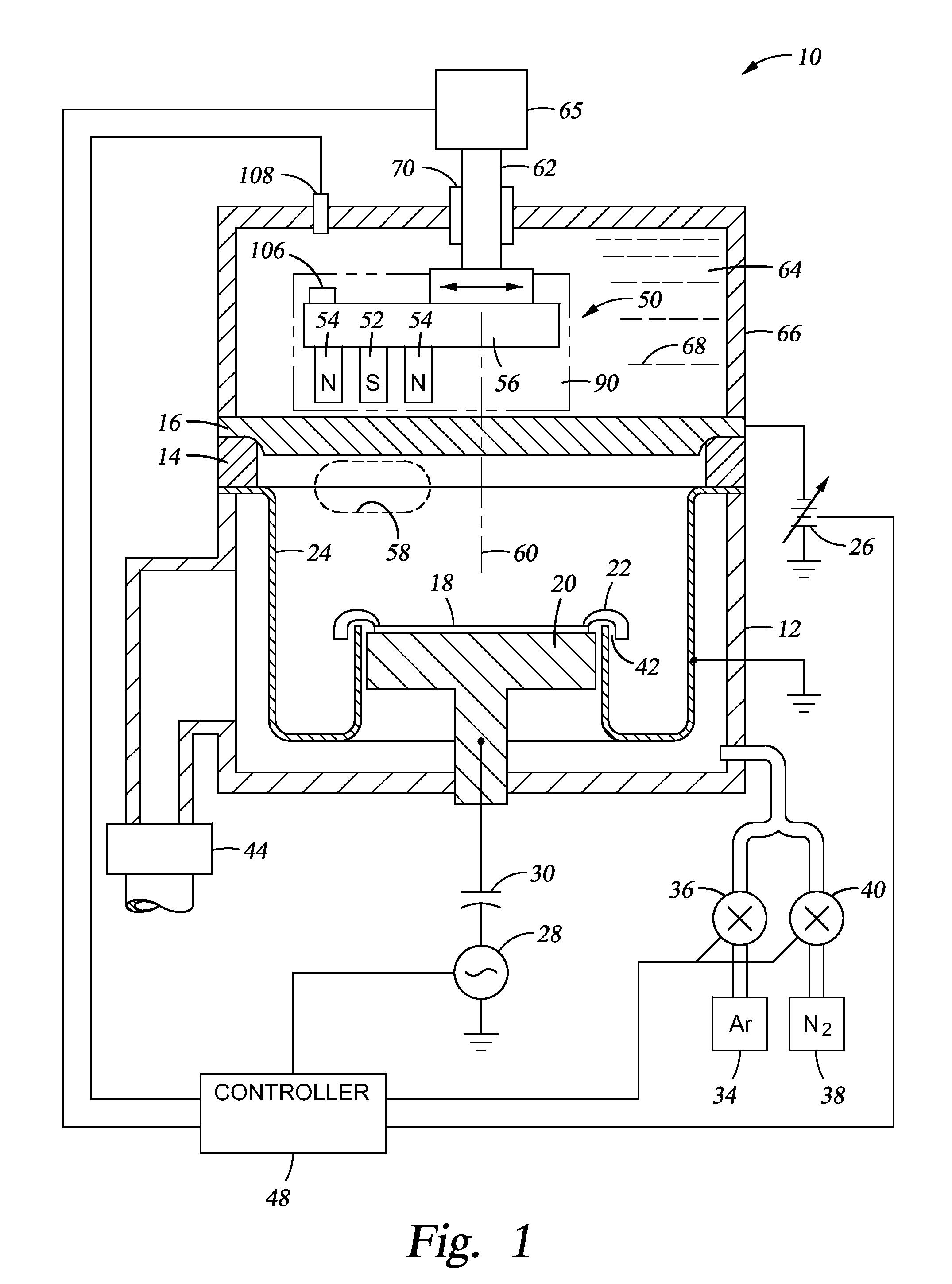
[0018]Embodiments described herein generally provide a magnetron that is encapsulated by a material that is tolerant of heat and water. FIG. 1 is a cross sectional view of a PVD chamber 10 according to one embodiment. The chamber 10 includes a vacuum chamber body 12 sealed through a ceramic insulator 14 to a sputtering target 16 having at least a front face composed of a material, usually a metal, to be sputter deposited on a wafer 18 held on a heater pedestal electrode 20 by a wafer clamp 22. Alternatively to the wafer clamp 22, a cover ring or an electrostatic chuck may be incorporated into the pedestal 20 or the wafer may be placed on the pedestal 20 without being held in place. The target material may be aluminum, copper, titanium, tantalum, cobalt, nickel, molybdenum, alloys of these metals containing less than 10 wt % of an alloying element, or other metals and metal alloys amenable to DC sputtering. On the other hand, RF sputtering may be used to sputter material from a diele...


PUM


Abstract

Embodiments of the present invention generally provide a magnetron that is encapsulated by a material that is tolerant of heat and water. In one embodiment, the entire magnetron is encapsulated. In another embodiment, the magnetron includes magnetic pole pieces, and the magnetic pole pieces are not covered by the encapsulating material.

Description

CROSS-REFERENCE TO RELATED APPLICATIONS[0001]This application claims priority to U.S. Provisional Patent Application Ser. No. 61 / 866,027, filed on Aug. 14, 2013, which herein is incorporated by reference.BACKGROUND[0002]1. Field[0003]Embodiments described herein generally relate to magnetrons used in physical vapor deposition process. In particular, embodiments described herein relate to an encapsulated magnetron.[0004]2. Description of the Related Art[0005]Physical vapor deposition (PVD), alternatively called sputtering, is a method of depositing layers of metals and related materials in the fabrication of integrated circuits. PVD was developed to deposit planar metal layers used for interconnects. Commercial PVD typically utilizes a plasma of a sputter working gas, such as argon, to bombard the negatively biased target with argon ions to sputter atoms of the target material, which thereafter coat a substrate with a layer of the target material. Plasma discharges are typically form...

Claims


Application Information

Patent Timeline
IPC IPC(8): H01J37/34H01J25/50H01J23/12
CPCH01J37/3405H01J25/50H01J23/12H01J37/345H01J23/05H01J23/10H01J25/587H03B9/10H03C3/32H03C5/04
Inventor WEST, BRIAN T.JOHNSON, ROGER M.COX, MICHAEL S.
Owner APPLIED MATERIALS INC
Why Eureka
Try Eureka