Brace system

a brace and system technology, applied in the field of braces, can solve the problems of needlessly heavy devices, bulky and awkward use, and poor performance of assistive braces, and achieve the effect of reducing the size and weight of the bra

Active Publication Date: 2015-02-19
BOSTON DYNAMICS INC
View PDF4 Cites 47 Cited by
  • Summary
  • Abstract
  • Description
  • Claims
  • Application Information

AI Technical Summary

Benefits of technology

[0027]Driving both brace assemblies removes the need for any rigid structures connecting between the medial and lateral arms. This reduces the size and weight of the brace and allows for width adjustment using straps. An additional advantage is that the hinge assemblies on t

Problems solved by technology

These devices are often heavy, bulky and awkward to use.
As a consequence, these devices are needlessly heavy, bulky and restricting, and they typically require custom-fitting to each user.
This problem is much worse for assistive (torque-producing) braces.
Mismatch between the instantaneous center of rotation of the hinge and of the knee causes uncomfortable or dangerous loads on the knee as well as making the brace migrate down the leg.
The mismatch is inevitable because the 1-DOF hinges are only an approximation of the motion of the knee and

Method used


Image

  • Brace system
  • Brace system
  • Brace system

Examples


Embodiment Construction

[0057]Aside from the preferred embodiment or embodiments disclosed below, this invention is capable of other embodiments and of being practiced or being carried out in various ways. Thus, it is to be understood that the invention is not limited in its application to the details of construction and the arrangements of components set forth in the following description or illustrated in the drawings. If only one embodiment is described herein, the claims hereof are not to be limited to that embodiment. Moreover, the claims hereof are not to be read restrictively unless there is clear and convincing evidence manifesting a certain exclusion, restriction, or disclaimer.

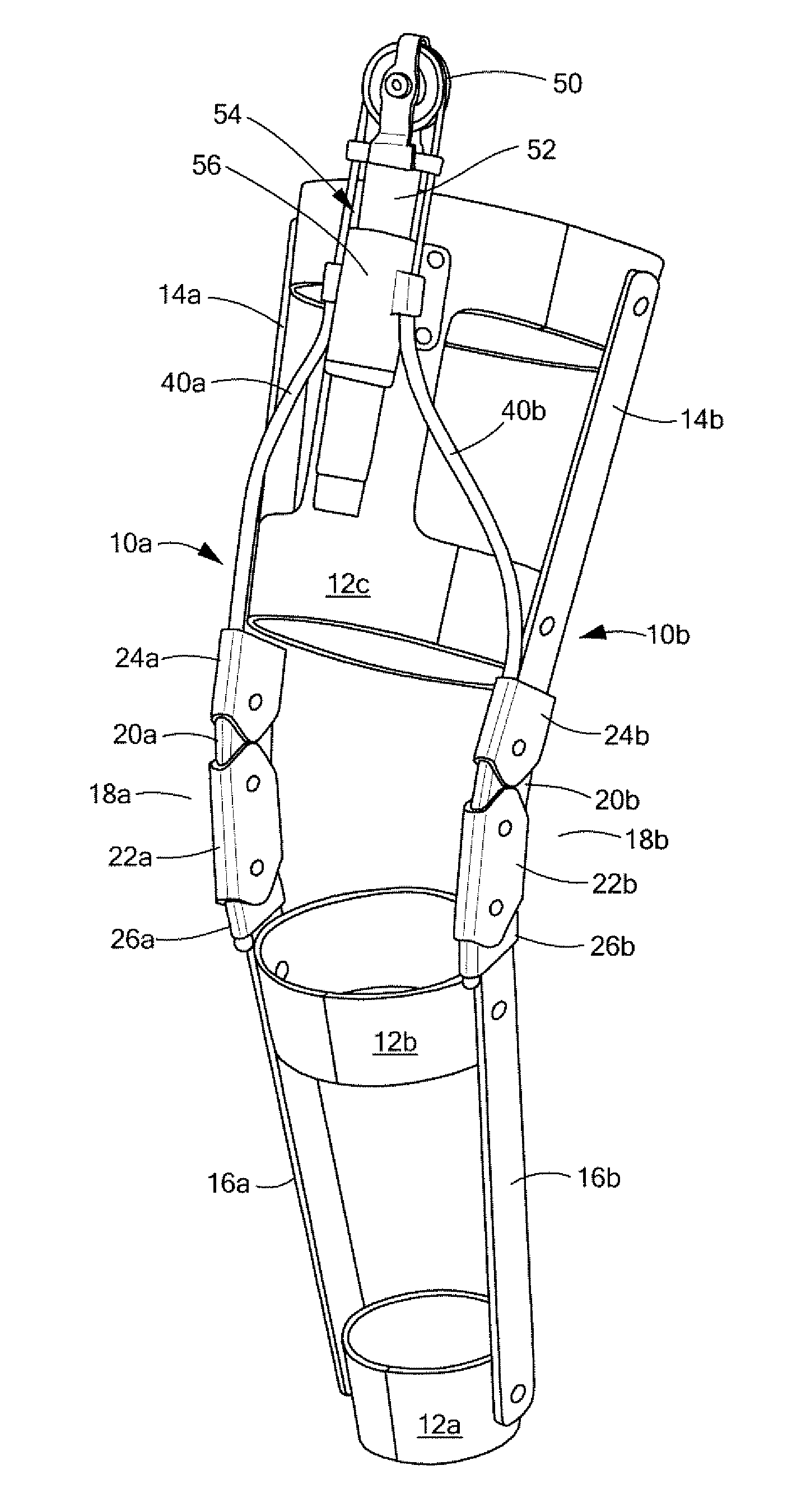
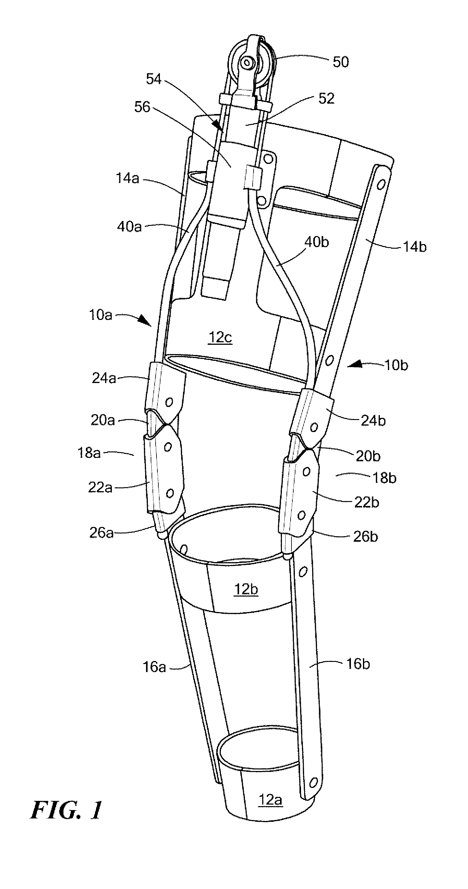
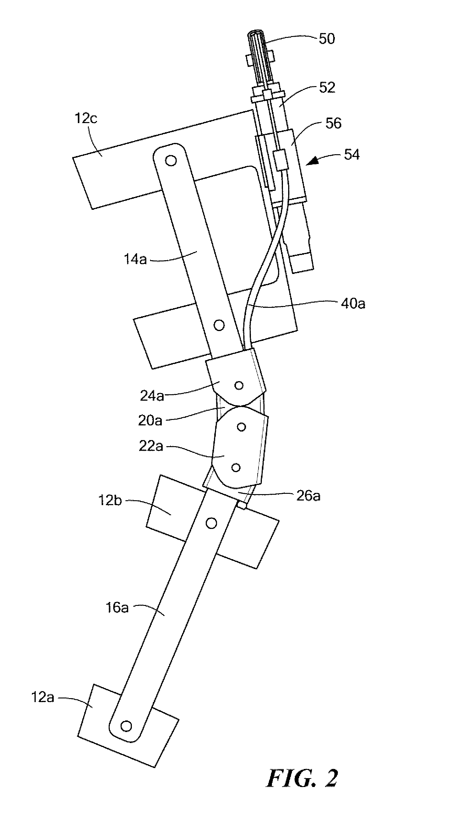
[0058]FIGS. 1-6 show one example of a brace system with medial brace 10a and lateral brace 10b. In some examples, there is only one brace but here braces 10a and 10b are securable about a leg, for example, via cross members 12a, 12b, and 12c (fabric with Velcro or other fasteners, plastic sleeve type configurations, or the ...


PUM


Abstract

A brace system includes a medial brace and a lateral brace securable via cross members. Each brace has an upper portion, a lower portion, and a hinge assembly between the upper and lower portion configured to allow translation of the lower portion relative to the upper portion.

Description

GOVERNMENT RIGHTS[0001]This invention was made with U.S. Government support under Contract No. W911 QX-12-C-0085 awarded by DARPA. The Government may have certain rights with regard to the invention.FIELD OF THE INVENTION[0002]The present invention relates to orthotics and exoskeletons. Aspects of the invention relate to braces which can assist the flexion or extension of a joint, e.g., the knee joint.BACKGROUND OF THE INVENTION[0003]Knee braces are varied in design. Most have one component strapped to the thigh and another component strapped to the calf with a pivotable link therebetween. See U.S. Pat. No. 4,372,298 incorporated herein by this reference.[0004]Other designs have a damper between two pivoting components and even sensors for controlling the damper. See U.S. Pat. No. 7,507,215 incorporated herein by this reference.[0005]Many knee braces are designed with rehabilitation in mind. Typically, natural knee joint motion is inhibited or constrained in some way.[0006]There is ...

Claims


Application Information

Patent Timeline
IPC IPC(8): A61F5/01
CPCA61F5/0125A61F2005/0137A61F2005/0139A61F2005/0144A61F2005/0169A61H1/024A61H3/00A61H2201/1246A61H2201/149A61H2201/1642A61H2201/165A61H2201/5061A61H2201/5071A61H2201/5084
Inventor POTTER, STEVEN D.THORNE, CHRISTOPHER EVERETTMURPHY, MICHAEL PATRICK
Owner BOSTON DYNAMICS INC
Why Eureka
Try Eureka