Auditory Prosthesis Using Stimulation Rate as a Multiple of Periodicity of Sensed Sound

Active Publication Date: 2015-02-19
MED EL ELEKTROMEDIZINISCHE GERAETE GMBH
View PDF3 Cites 9 Cited by
  • Summary
  • Abstract
  • Description
  • Claims
  • Application Information

AI Technical Summary

Problems solved by technology

That means that the time period between the actual zero crossing and the initial pulse of the p

Method used


Image

  • Auditory Prosthesis Using Stimulation Rate as a Multiple of Periodicity of Sensed Sound
  • Auditory Prosthesis Using Stimulation Rate as a Multiple of Periodicity of Sensed Sound
  • Auditory Prosthesis Using Stimulation Rate as a Multiple of Periodicity of Sensed Sound

Examples


Embodiment Construction

[0021]As discussed above, representation of the periodicity in an analog signal by a discrete system is inherently limited by its temporal resolution. For cochlear implants, this means that the highest stimulation rate (which is usually also the highest sensing rate) is the limit for the temporal resolution. If the input audio signal has a periodicity with a frequency f(a) and the sensing / stimulation rate of the CI system has a frequency f(e), a beating characterized by both frequencies is generated. Consequently, the electrical pulses may carry a jitter with respect to the zero crossing events. FIG. 5 illustrates this problem of the varying jitter between stimulation signals (solid lines) and sensing pattern (dashed lines). One way to reduce the problem of such jitter is to increase the sensing / stimulation rate. But that is rather energy consuming and ultimately has other technical limitations.

[0022]Embodiments are directed to reducing or eliminating unwanted jitter in auditory pro...


PUM


Abstract

A method is described for an auditory prosthesis system to generate electrical stimulation signals to stimulation contacts on an outer surface of an implanted electrode array. An input audio signal having a prominent sensed frequency is pre-processed to produce multiple representative frequency band signals. Each of the frequency band signals is then processed to generate corresponding electric stimulation signals for the stimulation contacts. Each of the electric stimulation signals has an associated stimulation frequency, and for at least one of the electric stimulation signals, the stimulation frequency is varied to maintain an integer ratio between the stimulation frequency and the prominent sensed frequency of the input audio signal.

Description

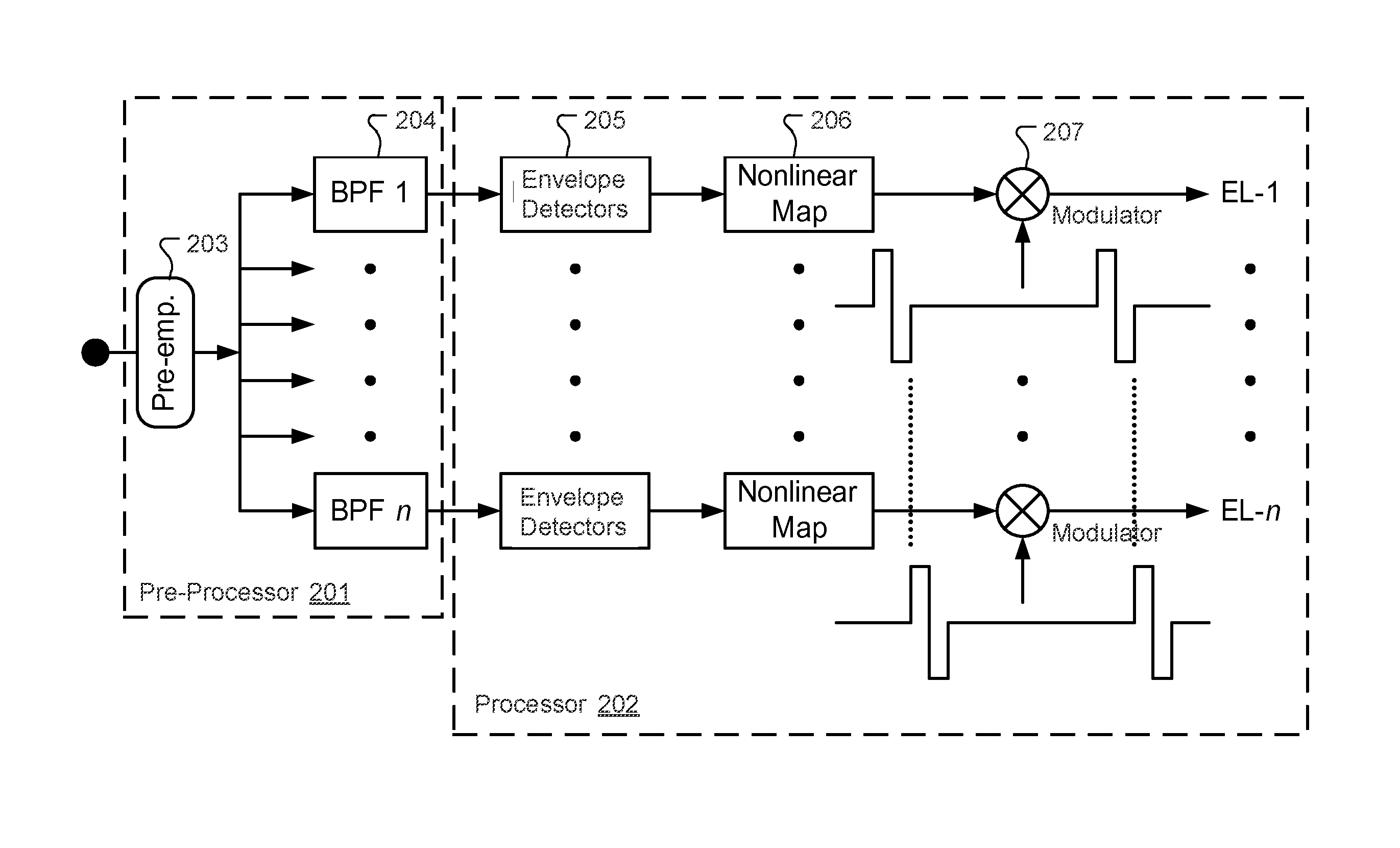
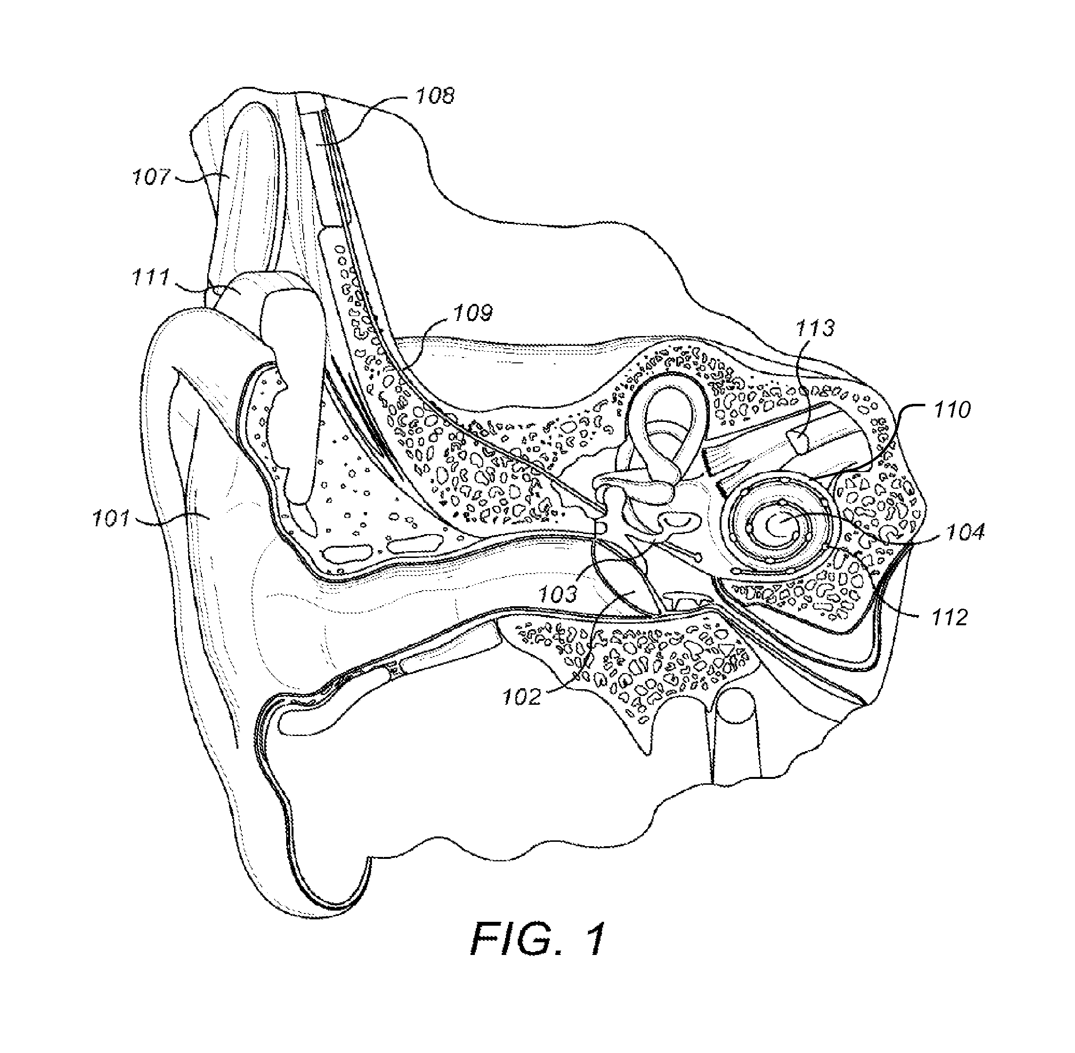
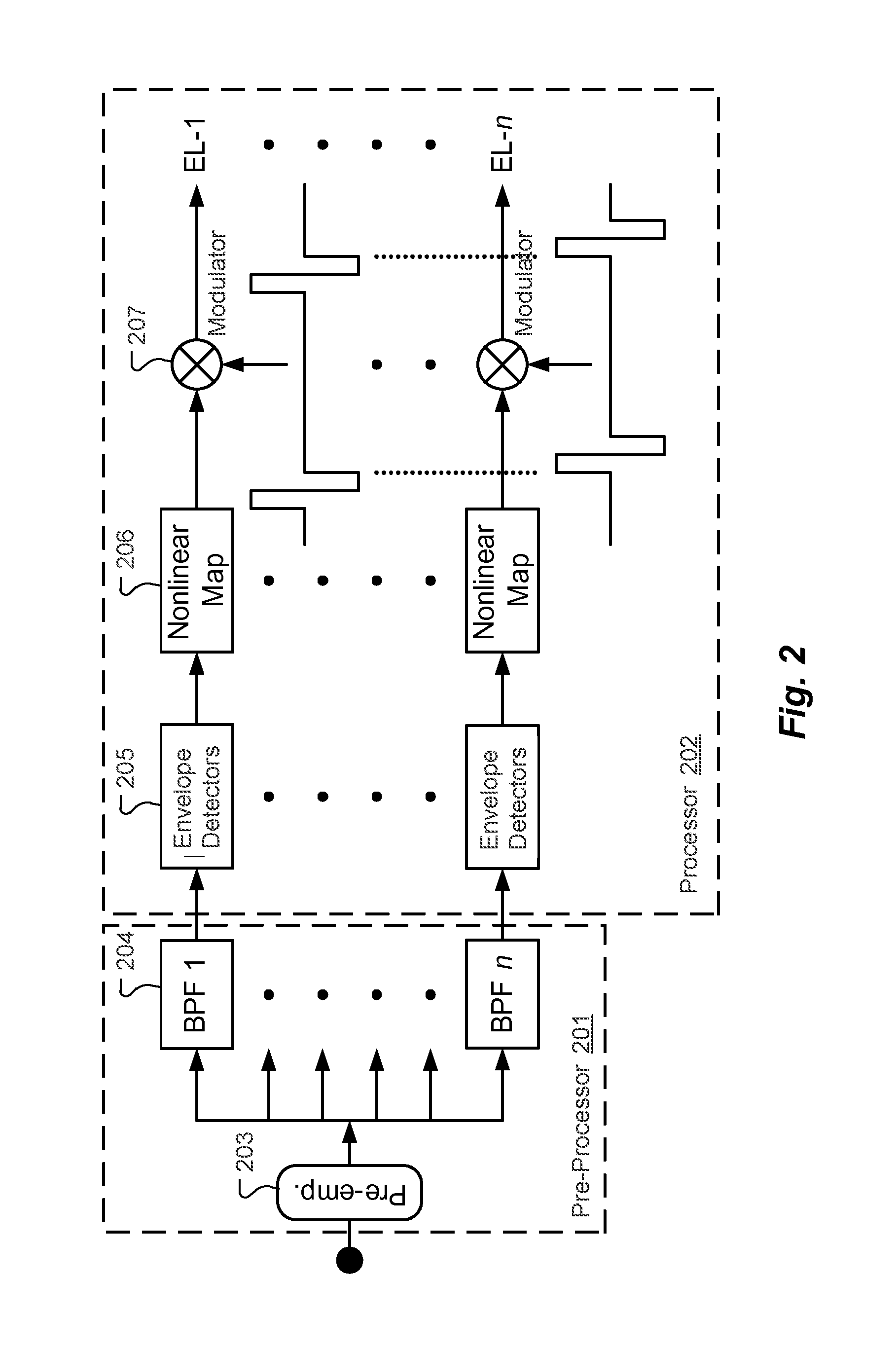
[0001]This application claims priority from U.S. Provisional Patent Application 61 / 867,200, filed Aug. 19, 2013, and from U.S. Provisional Patent Application 62 / 006,946, filed Jun. 3, 2014, which are incorporated herein by reference in their entireties.FIELD OF THE INVENTION[0002]The present invention relates to medical implants, and more specifically to electric stimulation techniques in cochlear implant systems and other implantable auditory prostheses.BACKGROUND ART[0003]A normal human ear transmits sounds as shown in FIG. 1 through the outer ear 101 to the tympanic membrane 102 which moves the bones of the middle ear 103 that vibrate the oval window and round window openings of the cochlea 104. The cochlea 104 is a long narrow duct wound spirally about its axis for approximately two and a half turns. It includes an upper channel known as the scala vestibuli and a lower channel known as the scala tympani, which are connected by the cochlear duct. The cochlea 104 forms an upright ...

Claims


Application Information

Patent Timeline
IPC IPC(8): H04R25/00A61N1/36
CPCH04R25/505A61N1/36032H04R2225/49H04R2225/023H04R2225/025A61N1/0541G09B19/00G09B23/28A61N1/36038
Inventor BAHMER, ANDREAS
Owner MED EL ELEKTROMEDIZINISCHE GERAETE GMBH
Why Eureka
Try Eureka