Pressure accumulator and percussion device

Active Publication Date: 2015-02-26
CONSTR TOOLS PC AB
View PDF6 Cites 3 Cited by
  • Summary
  • Abstract
  • Description
  • Claims
  • Application Information

AI Technical Summary

Benefits of technology

[0013]According to a further embodiment of the invention the pressure accumulator comprises at least one channel for hydraulic fluid, which at least one channel is in fluid communication with the impact piston's hydraulic fluid space, for example via a slide valve. According to another embodiment of the invention the pressure accumulator comprises a plurality of channels that is in fluid communication with the impact piston's hydraulic fluid space and that is arranged symmetrically around the

Problems solved by technology

A disadvantage with such solutions is that the part of the accumulator that projects out from the rest of the percussion device is exposed to impacts and to environmental effects.
Such solutions also make the percussion device harder to handle.
Furthermore, if a pressure accumulator is provided on an extension of a percussion device, the total length of the percussion device will be longer, which is of course a disadvantage for its use.
A disadvantage with the accumulator that is described in European patent number EP 0 947 293 is that if one wants to achieve a higher initial charging pressure in the accumulator, it has to contain a lot of small channels that extend in the radial direction, and the holes at the end of each channel have to be sufficiently small so tha

Method used


Image

  • Pressure accumulator and percussion device
  • Pressure accumulator and percussion device

Examples


Embodiment Construction

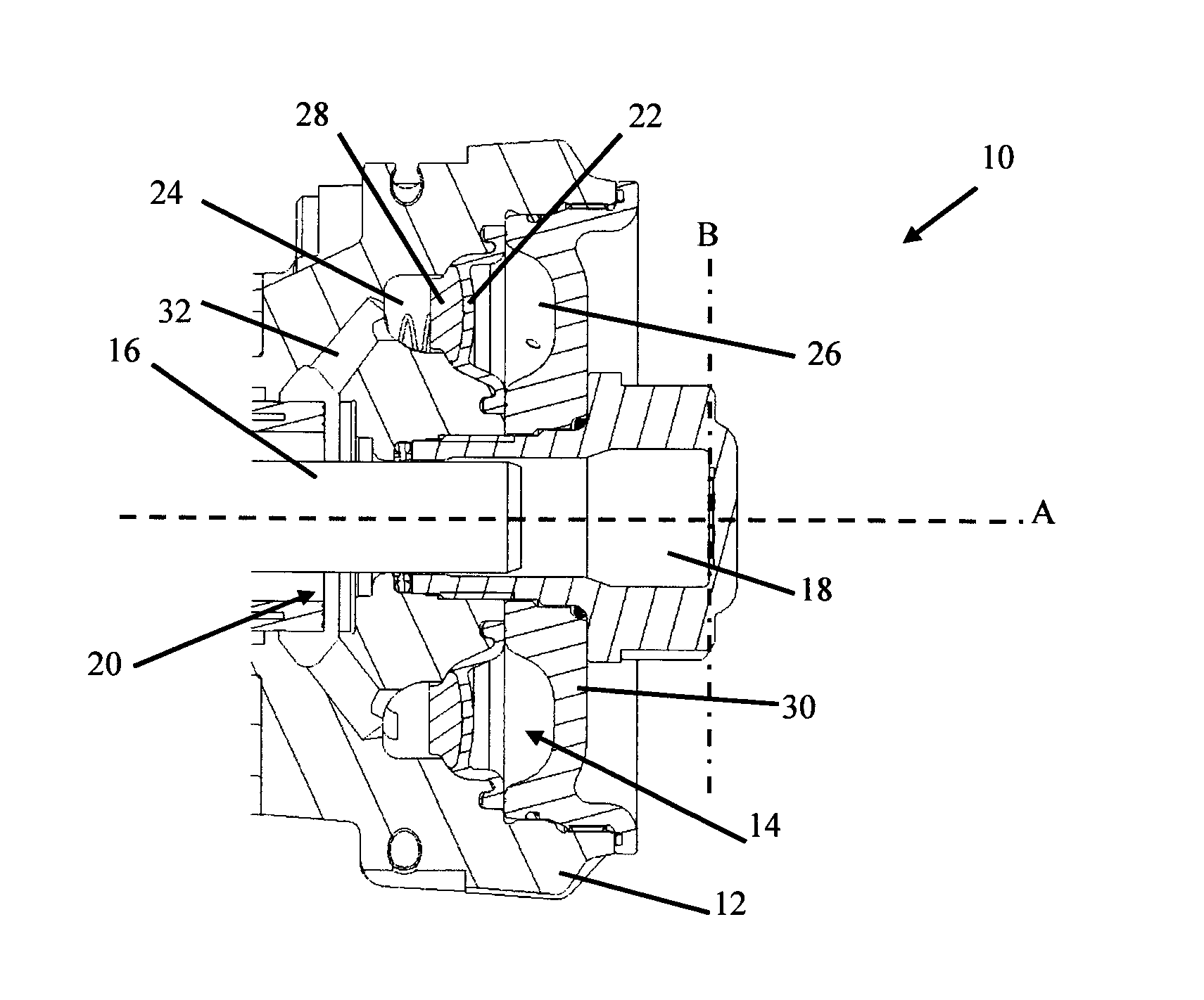
[0022]FIG. 1 shows the back part of a hydraulic fluid-driven percussion device 10 according to an embodiment of the present invention. The percussion device 10 comprises a rear portion 12 and a pressure accumulator 14 is integrated into the rear portion 12. The percussion device 10 comprises an impact piston 16 that is arranged to, in an impact piston chamber 18 whose upper impact space 20 is shown in FIG. 1, carry out a reciprocating motion caused by the pressure from the hydraulic fluid. The pressure accumulator 14 is arranged in communication with the impact piston's hydraulic fluid space via a slide valve.

[0023]The pressure accumulator 14 comprises a space, preferably a ring-shaped space, that extends around the impact piston 16, i.e. the whole of this ring-shaped space is arranged to extend around the impact piston chamber 18 in which the percussion device moves when the pressure accumulator 14 is mounted on the percussion device 10 without projecting out axially in front of or...


PUM


Abstract

A pressure accumulator for connection to a hydraulic fluid-driven percussion device. The percussion device includes at least one impact piston arranged to carry out a reciprocating motion caused by the pressure from the hydraulic fluid. The pressure accumulator is arranged in communication with a hydraulic fluid space of the impact piston. The pressure accumulator includes a space that extends at least partly around the impact piston when the pressure accumulator is mounted on the percussion device. A partition divides the space into two separate pressure chambers so that the pressure chambers are located an axial direction of the impact piston in relation to each other when the pressure accumulator is mounted on the percussion device. A first of the two separate pressure chambers is intended to be filled with a compressible medium. A second pressure chamber is in fluid communication with the hydraulic fluid space of the impact piston.

Description

TECHNICAL FIELD[0001]The present invention concerns a pressure accumulator and a hydraulic percussion device, for example an impact hammer, which comprises at least one such accumulator.BACKGROUND OF THE INVENTION[0002]A hydraulic percussion device often needs a pressure accumulator in order to even out pressure variations which arise from when the percussion device is in use. Pressure accumulators constitute a pressure-tight space, which is divided into at least two separate smaller spaces, for example by means of a pressure-tight membrane. A predetermined gas pressure is applied to a first side of the membrane. The pressurized gas may for example be nitrogen or some other suitable gas. A pressurized fluid that drives the membrane forwards may be provided on the second side of the membrane, which means that the pressure medium (the pressurized gas) on the first side of the membrane will be compressed. The pressure accumulator at the same time stores energy that can be released when...

Claims


Application Information

Patent Timeline
IPC IPC(8): B25D9/12
CPCB25D9/12B25D9/145F15B1/18F15B2201/205F15B2201/3151F15B2201/43F15B1/10
Inventor LUNDGREN, ANDERS
Owner CONSTR TOOLS PC AB
Why Eureka
Try Eureka