
Compact control device for failsafely controlling an electrical actuator

a control device and actuator technology, applied in relays, lifting equipment, transportation and packaging, etc., can solve the problems of unsafe stopping of weight, undesired opening of brake and therefore falling weight, and outputs of conventional safety pcs that are not designed to provide the high control current required for releasing elevator brakes, etc., to achieve the effect of simplifying the control of safety brakes

Active Publication Date: 2015-02-26
CHRISTIAN MAYR GMBH & CO KG
View PDF5 Cites 7 Cited by
  • Summary
  • Abstract
  • Description
  • Claims
  • Application Information

AI Technical Summary

Benefits of technology

The patent describes a small control device that simplifies the installation and commissioning of a safety brake. The device includes a failsafe monitoring system for the brake and can disconnect the control current in a safe manner, replacing two redundant contactors. The compact device achieves a significant improvement in safety brake actuation by integrating monitoring and evaluation functions, making it easier to install and operate compared to previous contactors. The technical effect of this refinement is improved safety and reliability in the operation of safety brakes.

Problems solved by technology

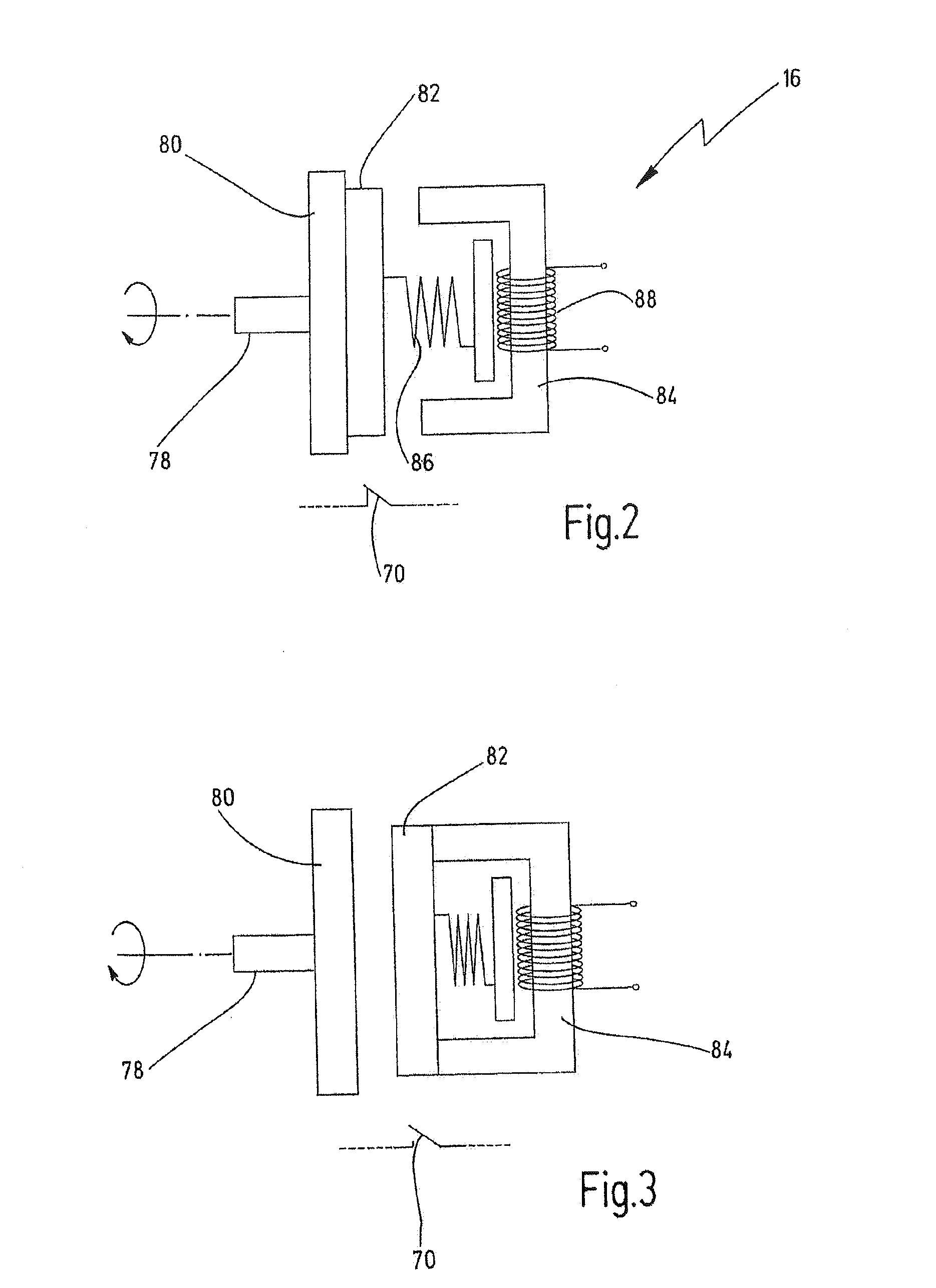
As soon as the current is interrupted, the armature plates press against the rotor again as a result of the spring force, with the result that the weight is safely stopped in the event of a power failure.
Switching-on and especially switching-off the current by the electromagnet is a safety-critical task since an undesired current flow, for example as a result of a fault in the electrical control system, can cause undesired opening of the brake and therefore falling of the weight.
However, the outputs of conventional safety PCs are not designed to provide the high control current required for releasing an elevator brake.
However, the time required for the disconnection is longer the more the overvoltage is limited.

Method used


Image

  • Compact control device for failsafely controlling an electrical actuator
  • Compact control device for failsafely controlling an electrical actuator
  • Compact control device for failsafely controlling an electrical actuator

Examples


Embodiment Construction

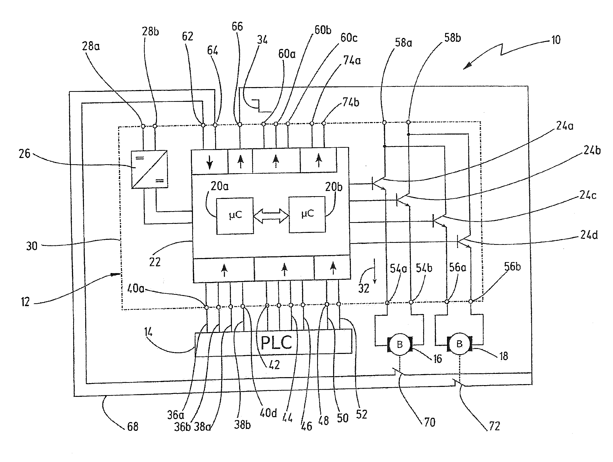
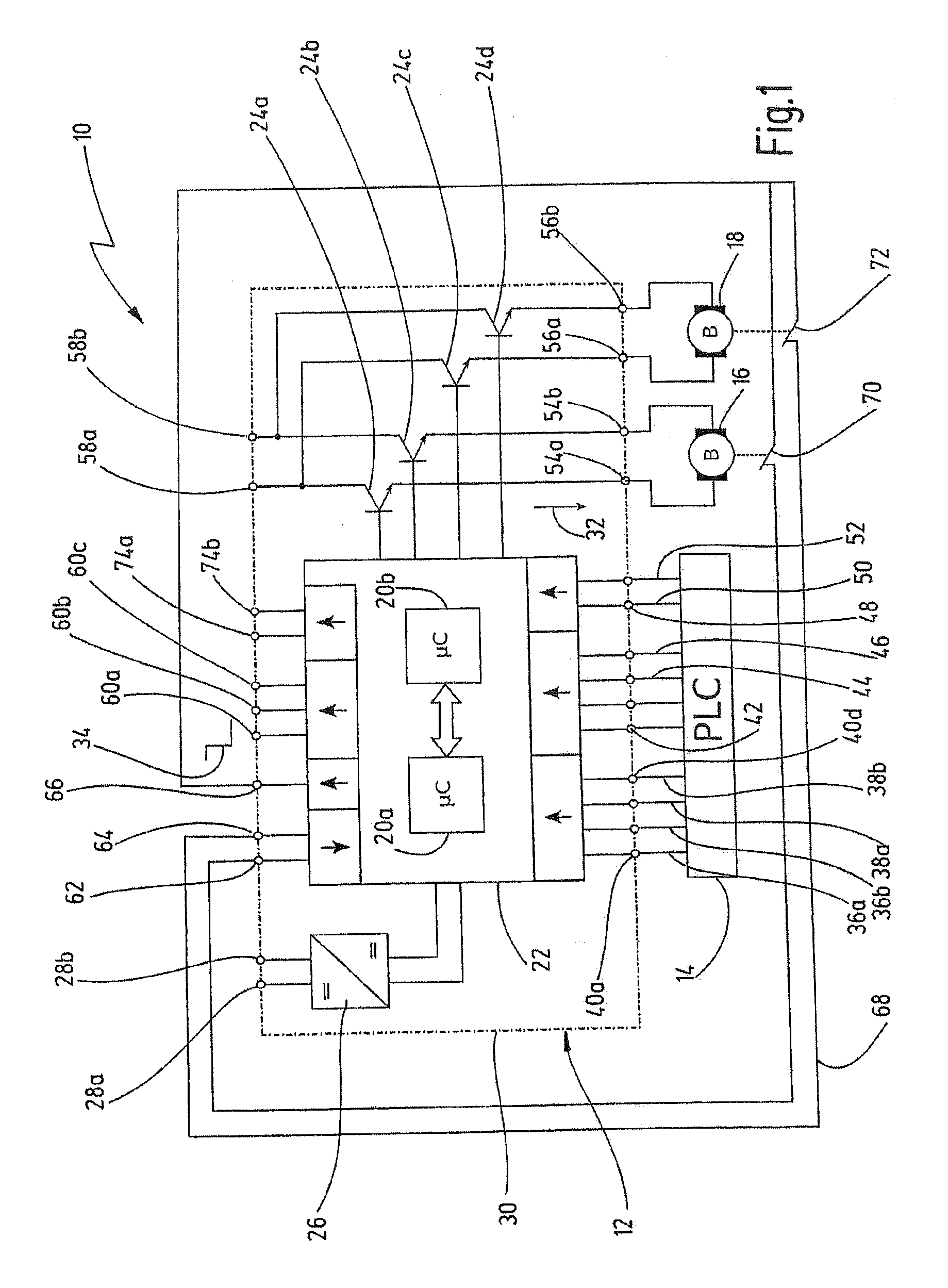
[0049]In FIG. 1, an apparatus including an exemplary embodiment of the novel compact control device is denoted in its entirety by reference numeral 10. The apparatus 10 comprises a compact control device 12, which is connected to a superordinate control system 14 via a plurality of connecting lines. The compact control device 12 in this case controls two redundant safety brakes 16, 18 depending on control signals which are provided by the superordinate control system. For example, the safety brakes 16, 18 are used in a redundant arrangement to prevent a passenger elevator or another weight from falling. The use of the novel compact control device is not restricted to the control of safety brakes, however. For example, the novel compact control device can, in other exemplary embodiments, be used for actuating solenoid valves and further, preferably inductive, electrical actuators in which a high control current is intended to be switched off in a failsafe manner.

[0050]In this exempla...


PUM


Abstract

A compact control device for failsafely controlling an electrical actuator capable of moving a movable machine part into a defined end position, has an input connection for receiving an external control signal representing a desired position of the machine part. The compact control device further has an input part for detecting a position signal, which signals an actual position of the machine part at the defined end position. A power section comprises a power switching element for switching on and failsafely switching off a control current for the actuator that is supplied to the electrical actuator via a first output connection. The compact control device has a second output connection for providing an external status signal and an evaluation unit which actuates the power switching element depending on the external control signal and generates the external status signal at the second output connection depending on the position signal.

Description

CROSS-REFERENCES TO RELATED APPLICATIONS[0001]This application is a continuation of international patent application PCT / EP2012 / 072823 filed on Nov. 16, 2012 designating the U.S., which international patent application has been published in German language and claims priority from German patent application DE 20 2012 101 654.0 filed on May 4, 2012. The entire contents of these priority applications are incorporated herein by reference.BACKGROUND OF THE INVENTION[0002]The present invention relates to a compact control device for failsafely controlling an electrical actuator, in particular for controlling a safety brake as is used, for example, in elevators and other movement axis affected by gravity. Furthermore, the invention relates to an apparatus for the failsafe holding of weights, such as an elevator or the like, comprising a mechanical brake and a compact control device.[0003]It is known to use safety brakes in order to safeguard elevators and other vertically raised weights a...

Claims


Application Information

Patent Timeline
IPC IPC(8): F16D65/14
CPCF16D2121/22F16D65/14B66D5/14B66D5/30
Inventor UNSIN, KARLHECHT, MARTINWIEGERT, ALEXANDERHAHN, ANDREASROESSLER, BERTHOLDHAERTER, MICHAEL
Owner CHRISTIAN MAYR GMBH & CO KG
Learn More