Heating elements for aircraft heated floor panels

Active Publication Date: 2015-02-26
THE BF GOODRICH CO
View PDF2 Cites 6 Cited by
  • Summary
  • Abstract
  • Description
  • Claims
  • Application Information

AI Technical Summary

Benefits of technology

[0007]A method of forming a heating element includes depositing a conductive ink of silver particles in an epoxy resin on a dielectric film to create

Problems solved by technology

While satisfactory for its intended purpose the traditional etch process can be time consuming, cause manufacturing difficulties and delay due to over- or u

Method used


Image

  • Heating elements for aircraft heated floor panels
  • Heating elements for aircraft heated floor panels

Examples


Embodiment Construction

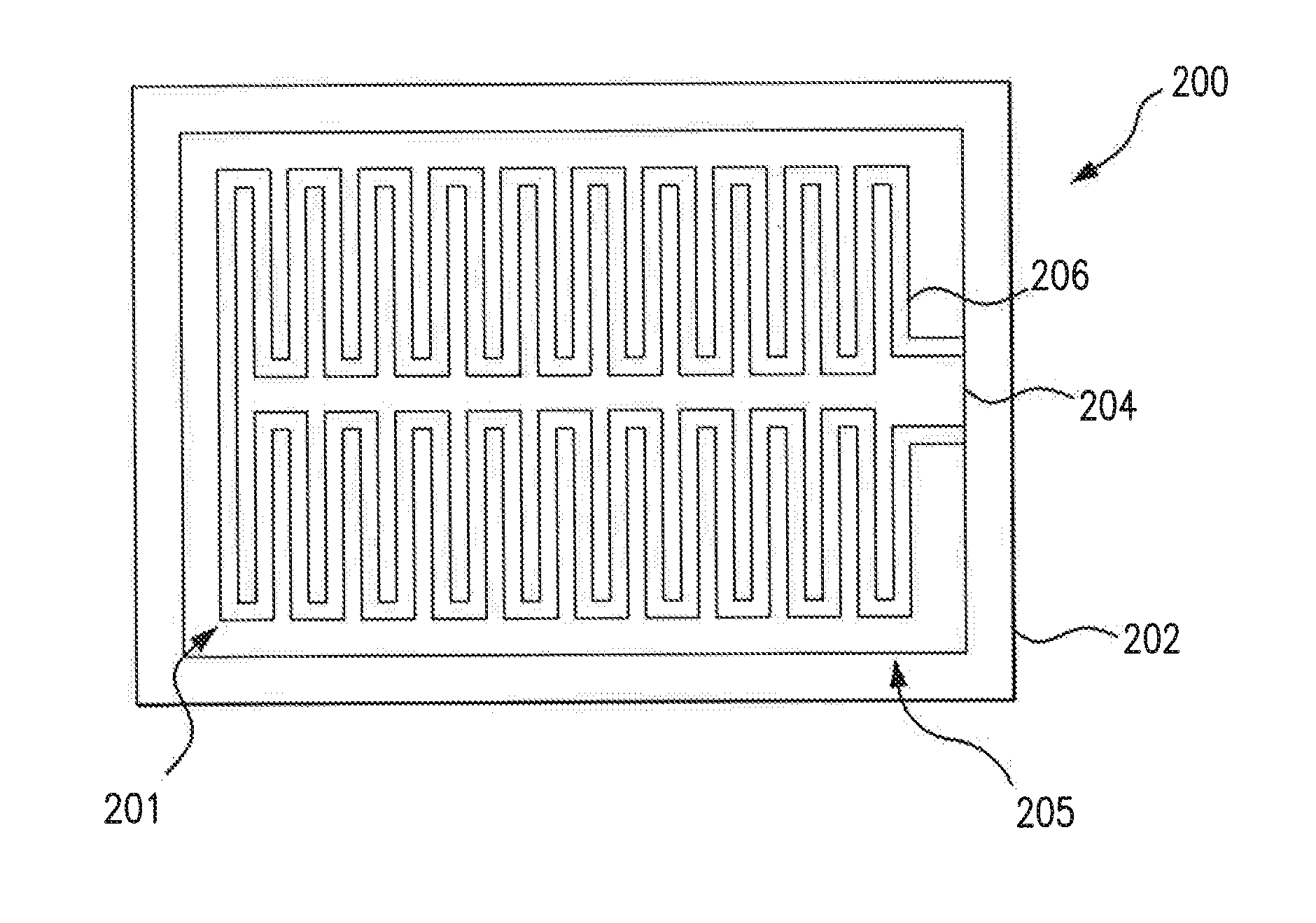
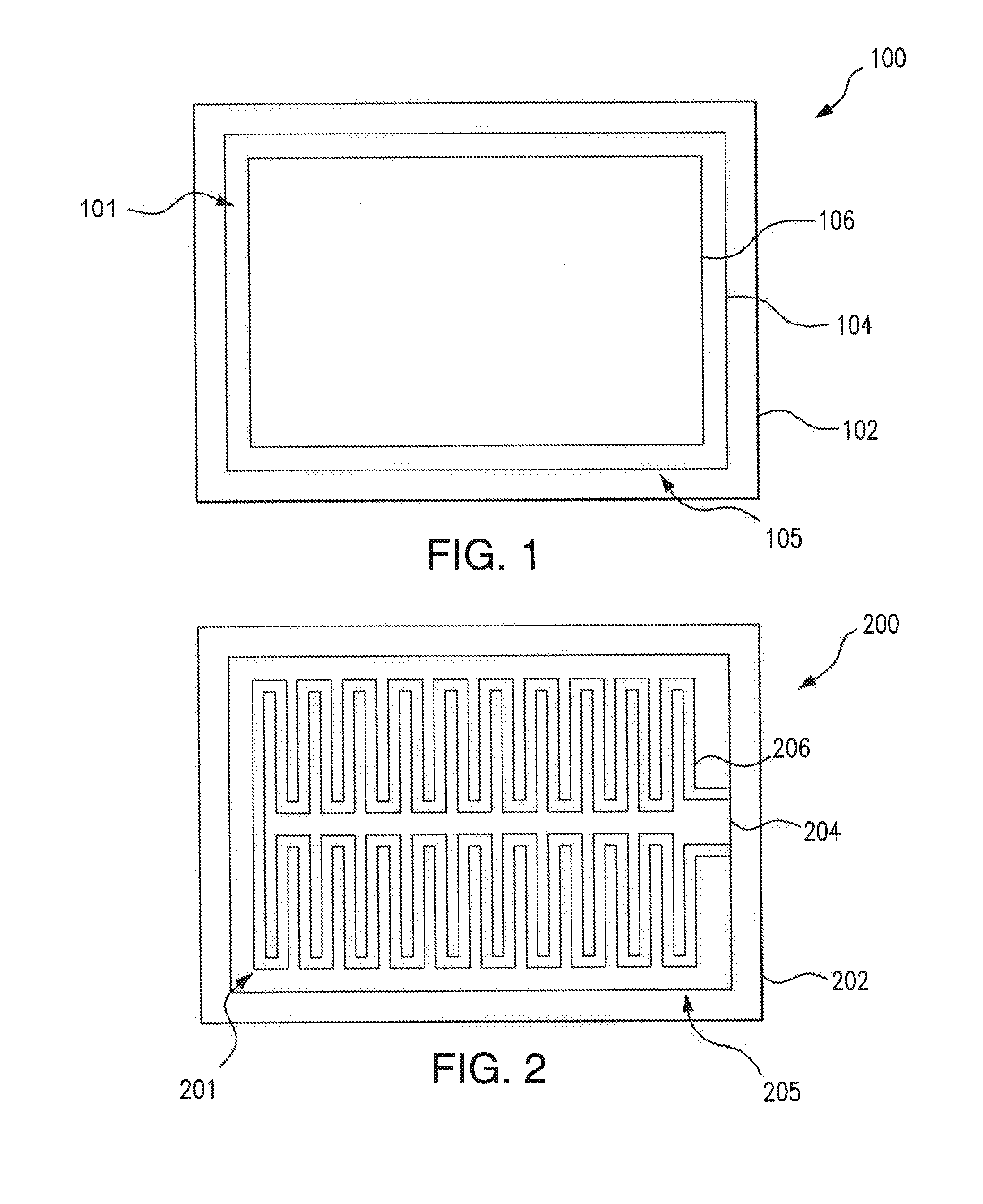
[0015]Reference will now be made to the drawings wherein like reference numerals identify similar structural features or aspects of the subject disclosure. For purposes of explanation and illustration, and not limitation, an exemplary embodiment of an aircraft heated floor panel in accordance with the disclosure is shown in FIG. 1 and is designated generally by reference character 100. Other embodiments of the aircraft heated floor panel in accordance with the disclosure, or aspects thereof, are provided in FIG. 2, as will be described. The systems and methods described herein can be used heating elements of heated floor panels, and / or other aircraft electrothermal heaters including ice protection systems for high power density, high temperature applications.

[0016]Screen printed resin-based conductive ink heating elements tend to be easier to manufacture than traditional chemically etched alloy resistive heating elements. Screen printed resin-based conductive inks, however, can requ...


PUM

PropertyMeasurementUnit
Temperatureaaaaaaaaaa
Lengthaaaaaaaaaa

Abstract

A method of forming a heating element includes depositing a conductive ink of silver particles in an epoxy resin on a dielectric film to create a conductive circuit, and heat curing the conductive circuit to achieve a resistivity of the heating element less than 1.68×10⁻⁶ ohm·meter. An aircraft heated floor panel includes at least one floor panel of an aircraft includes a conductive circuit positioned within the floor panel having a conductive ink of silver particles in an epoxy resin on a dielectric film.

Description

CROSS-REFERENCE TO RELATED APPLICATIONS[0001]This application claims priority to U.S. Provisional Patent Application No. 61 / 868,372, filed Aug. 21, 2013, to U.S. Provisional Patent Application No. 61 / 891,276 filed Oct. 15, 2013, and to U.S. Provisional Patent Application No. 61 / 891,292 filed Oct. 15, 2013, all of which are incorporated by reference herein in their entirety.BACKGROUND OF THE INVENTION[0002]1. Field of the Invention[0003]The present disclosure relates to heating circuits, and more particularly to resin-based conductive ink circuits.[0004]2. Description of Related Art[0005]Traditionally, resistive heating elements of heated floor panels are chemically etched alloy elements. The etch process is fairly involved and requires multiple steps. While satisfactory for its intended purpose the traditional etch process can be time consuming, cause manufacturing difficulties and delay due to over- or under-etch (making resistance too high or too low) or defects due to the photo-p...

Claims


Application Information

Patent Timeline
IPC IPC(8): B64C1/18H05K3/12B64D13/00
CPCB64C1/18B64D13/00H05K2203/12H05K3/1283H05K3/1216F24D13/024F24D2200/08F24D2220/2081H05B3/26H05B2203/003H05B2203/013H05B2203/017H05K1/167H05K2201/09263Y02B30/00Y10T29/49155Y10T29/49162H05B3/16H05K3/38
Inventor HU, JINHAMM, RICHARD R.ROACH, KEVIN E.
Owner THE BF GOODRICH CO
Why Eureka
Try Eureka