

Method and apparatus for sculpting parts and parts made therefrom
a technology of sculpting parts and machining methods, applied in the direction of manufacturing tools, instruments, transportation and packaging, etc., can solve the problems of limiting the maximum surface feet per minute of a cutter to approximately 135, high rotation speed of conventional spinning cutters, and poor thermal conductivity of titanium. , to achieve the effect of no post-machining polishing, no deburring, and no smoke finish
Inactive Publication Date: 2015-02-26
WILSON ALEXANDER
View PDF1 Cites 14 Cited by
- Summary
- Abstract
- Description
- Claims
- Application Information
AI Technical Summary
Benefits of technology
The invention is a new machining method that allows for smoother and more efficient removal of material from a work-piece. It uses a non-spinning cutter to carve off layers of material without causing striations or wear and tear on the cutter. The method produces a much smoother finish and requires less post-machining polishing. It also results in a work-product with less noise and reduced weight capacity. The method can be used to machine aluminum components with three-dimensional contouring, and it produces a surface finish with less striations and higher tolerances. Overall, the method is more efficient, tolerant, and produces better results than conventional methods.
Problems solved by technology
Conventional spinning cutters have a high rotation speed but typically have a relative low feed rate.
For example, titanium is a very poor thermal conducting material which limits the maximum surface feet per minute of a cutter to approximately 135 surface feet per minute.
Method used
View moreImage
Smart ImageViewing Examples

Examples
example 1
[0074]The sculpting method of machining offers a significant reduction in the cost of cutting tools. For example, a moderately sized aircraft component made from titanium metal was shown to consume a cost of $50 in cutters to produce just one part when using traditional milling method of machining. With the sculpting method of machining the cost was reduced to just $1 in cutter cost to produce the same part.
Login to View More PUM
| Property | Measurement | Unit |
|---|---|---|
| length | aaaaa | aaaaa |
| RA | aaaaa | aaaaa |
| surface roughness | aaaaa | aaaaa |
Abstract
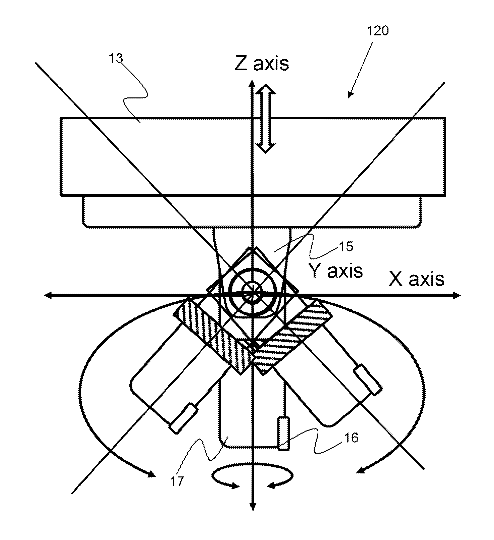
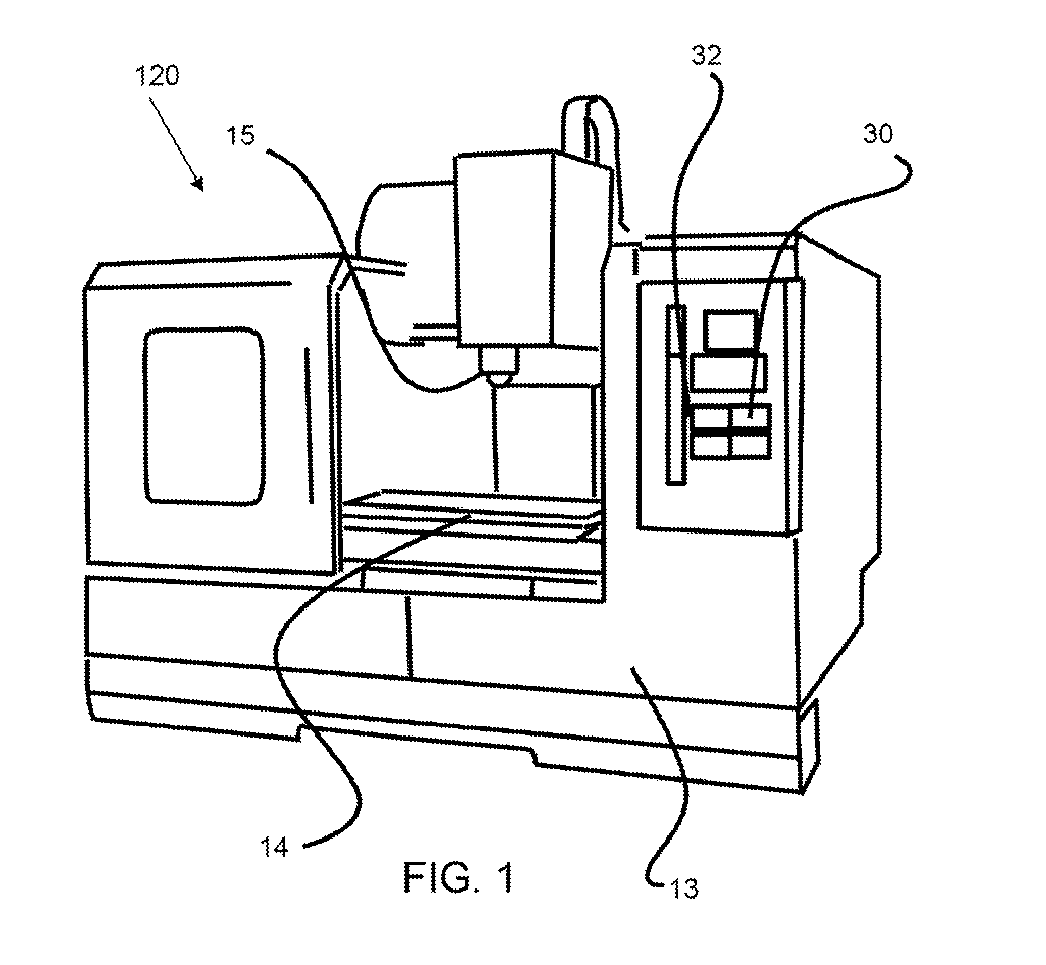
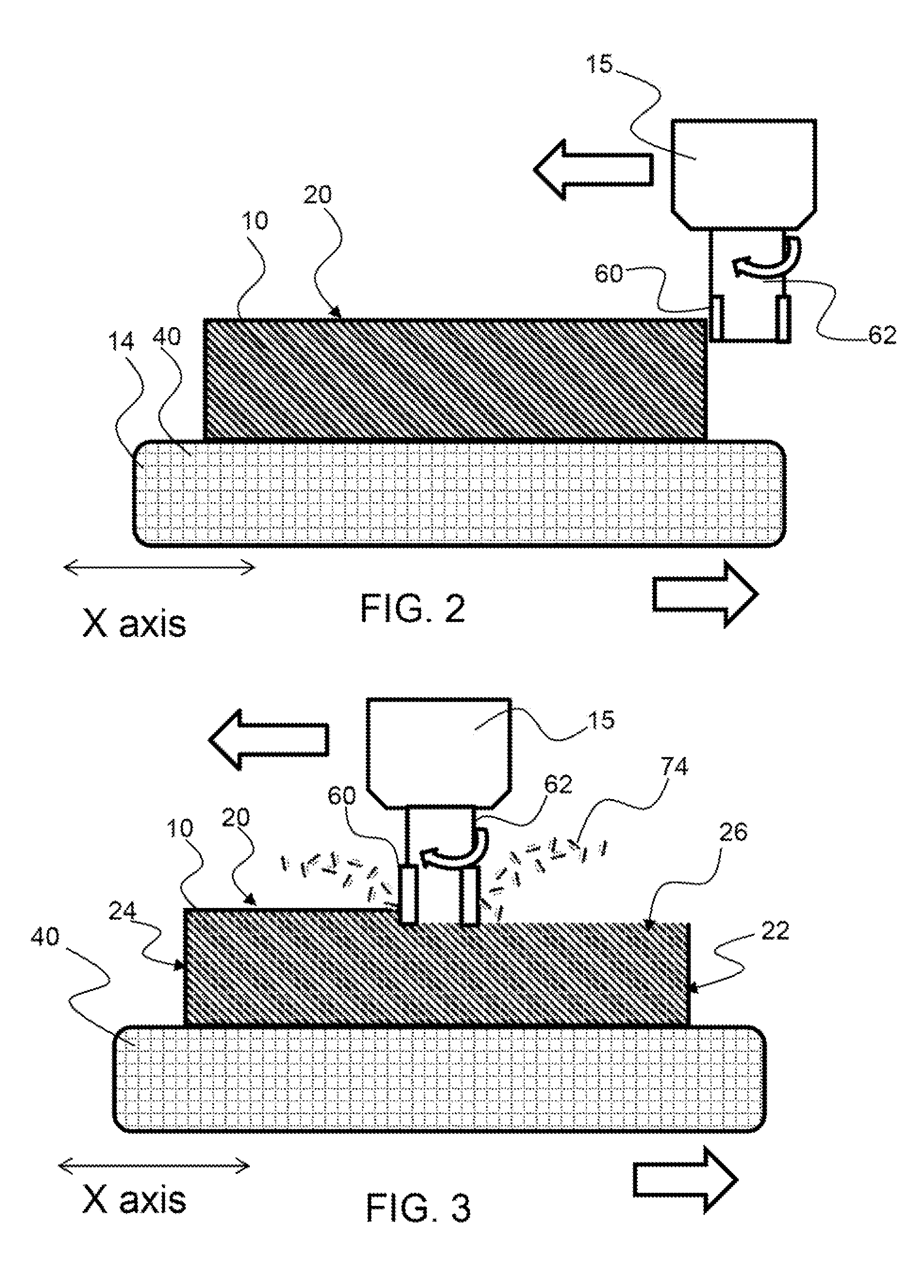
A sculpting machine, a method of sculpting a work-piece and work-products produced therefrom are described. A sculpting machine provides a cutting tool holder that is configured to hold a cutter in contact with a work-piece and move in two or more planes or axes of controlled motion about the work-piece to remove material. The cutter is non-spinning and is held in contact with the work-piece to carve away material, or sculpt the work-piece. The cutter may be held against the work-piece with the cutter in a fixed orientation relative to the surface of the work-piece being cut. The cutter may be moved along a straight line, curve or arc. The resulting product produced may have a much tighter tolerance and smoother surface finish than products machined with conventional techniques.
Description
CROSS REFERENCE TO RELATED APPLICATIONS[0001]This application claims the benefit of U.S. provisional patent application no. 61 / 869,708, filed on Aug. 25, 2013 and entitled Method and Apparatus for Sculpting Parts and Parts Made Therefrom, of which the entirety is incorporated by reference herein.BACKGROUND OF THE INVENTION[0002]1. Field of the Invention[0003]The present invention relates to a unique sculpting machining method, an apparatus for sculpting parts and parts made therefrom.[0004]2. Background[0005]The current way of machining parts with a computerized numerical control, CNC, milling machine utilizes spinning cutting tools. The cutting tools, which are comprised of end mills, face mills, drills, etc., are designed to spin in a spindle of a CNC machine. The speed at which they spin is determined by the type of material being machined and also by the physical limitation of the machine. Typical spindle spinning speeds range from 10 rpm to about 30,000 rpm. While a spinning cu...
Claims
Login to View More Application Information
Patent Timeline
 Patent Type & AuthorityApplications(United States)
IPC IPC(8): B23D5/02B23D7/06
CPCB23D7/06B23D5/02Y10T409/500164Y10T428/24355Y10T428/24479
InventorWILSON, ALEXANDER
OwnerWILSON ALEXANDER